


Pelco Manual C546M (8/98) 9
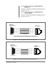
Figure 6. Pin Connections Between a CM9760-PEX and a Multiplexer
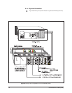
Figure 7. Pin Connections Between a CM9760-PEX and CM9760-KBD
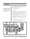
3.1.3.3 Connection Between a CM9760-PEX and
Multiplexers
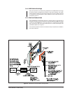
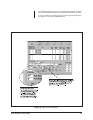
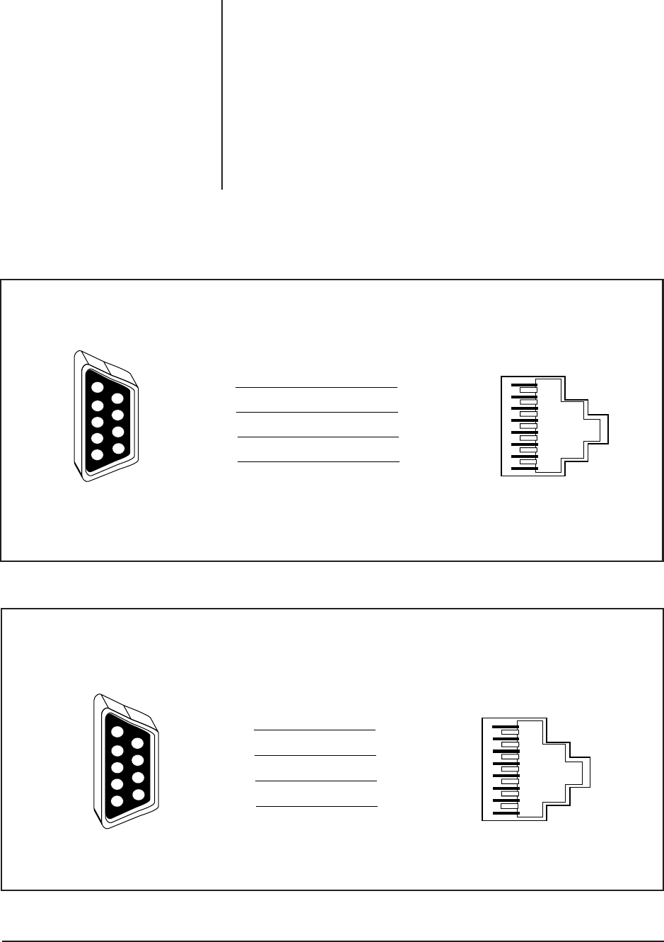
The connection of a Multiplexer to a CM9760-PEX is illustrated in Figure 6. One
Multiplexer can be connected to each comms port on a Port Expander card (up to
eight Multiplexers per card).
3.1.3.4 Connection Between a CM9760-PEX and
Pelco Keyboards
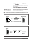
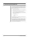
The connection of a CM9760-KBD to a CM9760-PEX is illustrated in Figure 7. One
keyboard can be connected to each comms port on a Port Expander card (up to
eight CM9760-KBDs per card).
COMMS PORT
CM9760-PEX
DB9 PORT (FEMALE)
DB9 (FEMALE)
1
2
3
4
5
6
7
8
DATA PORT IN
RJ-45 (FEMALE)**
RJ-45 (FEMALE)
PIN 4 = (Rx +)
PIN 8 = (Rx –)
PIN 5 = (Tx +)
PIN 9 = (Tx –)
PIN 1 = (Tx +)
PIN 2 = (Tx –)
PIN 8 = (Rx +)
PIN 7 = (Rx –)
RS-422 COMMS
**PINOUT EXAMPLE USED IS FOR THE MX4000 GENEX™ MULTIPLEXER.
CONSULT MANUFACTURE’S DOCUMENTATION FOR OTHER MULTIPLEXERS.
6
7
8
9
1
2
3
4
5
1
2
3
4
5
6
7
8
CM9760-CC1
SERCOM 8 PORT
(FEMALE)
RJ-45 (FEMALE)
PIN 4 = (Rx +)
PIN 8 = (Rx –)
PIN 5 = (Tx +)
PIN 9 = (Tx –)
PIN 1 = (Tx +)
PIN 2 = (Tx –)
PIN 8 = (Rx +)
PIN 7 = (Rx –)
COMMS PORT
CM9760-PEX
DB9 PORT (FEMALE)
DB9 (FEMALE)
6
7
8
9
1
2
3
4
5