


2 Pelco Manual C1423M-D (10/03)
REVISION HISTORY
Manual # Date Comments
C1423M 6/95 Original manual.
C1423M-A 4/96 Rev. A. Incorporated Manual C1424M for blower kits.
Incorporated Manual C1425M for defroster kits. Added
instructions for installation of O/I-PCB circuit board kit.
Added Operation and Care and Maintenance sections.
5/98 Removed references to continuous duty operation of
the heaters and defroster. Changed manual to new
format.
C1423M-B 8/98 Rev. B. Metal plate was added to defroster per ECO#
98-3887. Added certification information.
C1423M-C 7/01 Revised defroster kit installation instructions.
C1423M-D 10/03 Revised heater kit installation instructions, step 5b.
CONTENTS
Section Page
1.0 GENERAL ..................................................................................................3
1.1 IMPORTANT SAFEGUARDS AND WARNINGS ...............................3
2.0 DESCRIPTION ..........................................................................................4
2.1 CERTIFICATIONS .............................................................................4
3.0 BLOWER KIT INSTALLATION ...................................................................5
4.0 HEATER KIT INSTALLATION ....................................................................9
5.0 DEFROSTER KIT INSTALLATION............................................................ 11
6.0 CIRCUIT BOARD KIT INSTALLATION .....................................................13
7.0 OPERATION .............................................................................................17
8.0 CARE AND MAINTENANCE ....................................................................17
8.1 TROUBLESHOOTING ......................................................................17
9.0 WARRANTY AND RETURN INFORMATION ...........................................20
LIST OF ILLUSTRATIONS
Figure Page
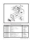
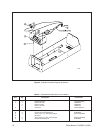
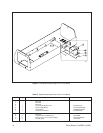
1 Exploded Assembly Diagram for Blower ............................................8
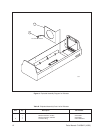
2 Exploded Assembly Diagram for Heaters .........................................10
3 Exploded Assembly Diagram for Defroster ....................................... 12
4 Exploded Assembly Diagram for Circuit Board ................................. 14
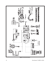
5 Input Wiring Diagram ........................................................................16
6Wiring Diagram for Optional Circuit Board (O/I-PCB) .......................18
7 Circuit Board Component Locations .................................................19
8 Circuit Board Layout of Traces .......................................................... 19
LIST OF TABLES
Table Page
A 24 VAC Wiring Distances ...................................................................6
B Exploded Assembly Parts List for Blower ..........................................8
C Exploded Assembly Parts List for Heaters........................................10
D Exploded Assembly Parts List for Defroster .....................................12
E Exploded Assembly Parts List for Circuit Board ...............................14