8 Pelco Manual C1423M-D (10/03)
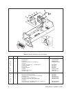
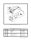
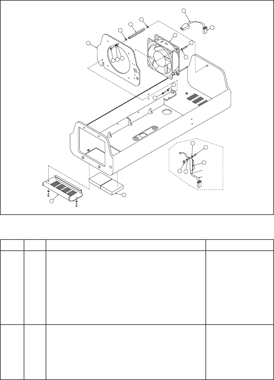
Table B. Exploded Assembly Parts List for Blower
Item Qty Description Part Number
11 Vent Grill, Beige 57004105COMP
1Vent Grill, Gray 57004005COMP
22 Foam Filter EH550010045
31 24 VDC Fan Rectifier (for -2 model only) PCB9000277ASSY
4-7 Not Used
81 Fan Wire Cord with Plug (-1, -3 models only) WIR432000
91 Fan Tube, 230 VAC ED210015
1 Fan, 24 VDC 955105W3
1 Fan Tube, 120 VAC EH18013
10 1 Fan Plate 57004010COMP
11 1 Standoff, 3.375" Length 570010007
12 1 Connector Plug CON1-480318-0
A3 Cap Screw, 6-32 x 3/8", Allen Socket Head ZH6-32X.375CS
B8 Internal Tooth Lock Washer, #6 ZH6LWSIS
9 Internal Tooth Lock Washer, #6 (for -2 model only) ZH6LWSIS
C2 Flat Washer, #6 ZH148X375X32C
3 Flat Washer, #6 (for -2 model only) ZH148X375X32C
E4 Cap Screw, 6-32 x 3/8", Allen Socket Head ZH6-32X.375CS
F-H Not Used
J1 Screw, 6-32 x 1/2", Pan Head, Phillips (for -2 model only) ZH6-32X.500SPP
K1 Hex Nut, 6-32 (for -2 model only) ZH6-32NUTSH
Figure 1. Exploded Assembly Diagram for Blower
10
C
11
B
8
12
E
9
C
B
A
B
B
A
TO
FAN
C
J
3
K
B
RED
22 GA. (1 FT.)
BLACK
22 GA. (1 FT.)
TO CIRCUIT
BOARD
1
2
00968


