Pelco Manual C411M-D (1/96) 3
NOTE: Cameras with a low optical centerline
or using a large diameter lens require an eleva-
tion block (1 inch or 2 inch) for proper posi-
tioning. See Section 8.0, Optional Accessories,
for the correct model number.
3. Replace the camera/sled assembly onto the rail and
slide along the rail to adjust the camera to maxi-
mum forward camera position; lock into place by
tightening the Allen head screws.
IMPORTANT: Set the focus for the shortest
distance to extend the lens to the maximum
length before positioning the camera/lens com-
binations. This will ensure that the lens has
enough clearance and will not hit the window
during focusing.
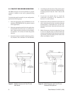
4. Loosen the cable gland nuts on the back of the
enclosure (1/2-inch gland for video cable, 3/8-inch
gland for power cable). Route the camera cables
through the appropriate glands and connect to the
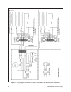
camera. Wire the enclosure per wiring diagram
provided (see Figure 2). Tighten the gland nuts for
a snug fit around the cables.
NOTE: The plate holding the two cable glands
on the bottom of the enclosure is removable,
which allows enough clearance for the connec-
tor assemblies to be inserted in or removed from
the enclosure. This permits the connectors (i.e.,
lens connector, video connector, etc.) to be as-
sembled somewhere other than the field and
also allows the enclosure to be moved in the
field without disassembling all the connectors.
5. Replace the lid and secure the latches.
6. Attach the enclosure to the appropriate mount or
pan and tilt using the instructions provided with the
mounting equipment.
4.0 INSTALLATION
Please check the contents of your package(s) for the
following items before proceeding with the installation
of the equipment.
Quantity Item
2 1/4-20 x .500 hex head screws to mount
camera
1 5/32-inch Allen wrench for adjusting sled
1 Blower assembly (installed on models
with “HB” in suffix only)
1 Heater assembly (installed on models with
“HB” in suffix only)
2 Keys (for models with “L” in suffix only)
4.1 ELECTRICAL CONNECTIONS –
ENCLOSURES WITH BLOWER AND
HEATER
Factory installed heater and blower assemblies are
factory pre-wired and only require connection of power
to the terminal block (see Figure 2). Refer to Section 4.6
for field installed heater/blower kits.
NOTE: In dusty locations, double filters can
be installed. Loosen the two Allen head screws
at the rear of the enclosure and pull the drawer
open. Remove the acorn nuts at the rear of the
housing and pull the end plate off for access to
the filters.
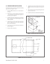
4.2 INSTALLATION OF CAMERA/LENS
To install the camera/lens, perform the following:
1. Remove the lid by unlatching the two latches on
each side.
2. Remove the camera sled from the rail by loosening
the two Allen head screws and attach the camera/
lens with the 1/4-20 hex head screws provided.


