


C1309M-A (9/08) 13
FIELD SETUP
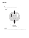
DISASSEMBLE THE ENCLOSURE
1. Use the supplied 1/8-inch hex wrench to loosen the two captive hex screws on the enclosure’s back plate.
2. Pull the “T” handle on the enclosure’s back plate to remove the enclosure sled.
3. Disconnect the ground cable from the ground stud on the inside of the enclosure’s back plate.
4. Use the supplied 5/64-inch hex wrench to remove the two screws on the enclosure’s front plate, as shown in Figure 3 on page 9. Do not
loosen the third screw.
5. (From the back of the enclosure) Carefully push the camera assembly through the front of the enclosure by applying pressure to the metal
part of the chassis.
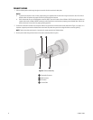
CONNECT WIRING
1. Pull the shielded power cable and shielded serial cable through the gland on the left side of the enclosure’s back plate.
NOTES:
• If the serial cable will be permanently installed, replace the left gland with a liquid-tight multihole gland (not supplied). Use a gland
similar to a Heyco
®
liquid-tight multihole cordgrips.
• To prevent the entrance of dust or water, proper cabling (not supplied) must be used when wiring the enclosure. Use of flat cable or
multiple cables will prevent the proper seal of the liquid-tight gland connectors.
• Pelco recommends the use of shielded power and serial cables. Use a serial cable similar to Belden 1624P Cat5 equivalent cable; use
a power cable similar to Belden 5300FE twisted-pair cable. Special care must be taken to properly ground shielded cable. Refer to the
cable manufacturer’s instructions for proper grounding practices.
2. Connect the shield drain conductors from both the power and serial cables to the ground stud on the enclosure’s back plate (refer to
Figure 1 on page 7). It is important to properly terminate shielded cables at both ends to protect the system from voltage transients caused
by lightning.
NOTE: Refer to the cable manufacturer’s instructions for proper termination of shielded cable.
3. Run the power cable and serial cable through the enclosure to the camera assembly (refer to Figure 4 on page 10).
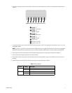
4. Connect the input power wiring for either 24 VDC or 24 VAC to the screw terminals for pins 6 and 7 on the detachable connector (refer to
Figure 5 on page 11).
5. Connect the serial communication interface wiring coming from your PC to the appropriate screw terminals for pins 1–4 on the detachable
connector.
NOTES:
• If your PC is using RS-232 communication and the TI2500 Series device is using RS-422 communication, you must use an appropriate
RS-232/RS-422 converter. Pelco recommends the use of a converter comparable to B&B Electronics universal converter (model
4WSD9R).
• The serial cable should be 100-ohm impedance shielded twisted pair. If you are using RS-232 communication, the cable length should
be no longer than 50 ft; if you are using RS-422 communication, the cable length should be no longer than 4,000 ft.
6. Pull the unterminated end of your RG-59 or RG-6 video cable through the gland on the right side of the back plate of the enclosure.
7. Run the video cable through the enclosure to the camera assembly.
8. Crimp a BNC connector onto the end of the video cable. Connect the video cable BNC connector onto the camera assembly BNC connector.
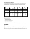
9. Set the DIP switches to either RS-232 or RS-422 communication and termination (refer to Table A on page 11).
WARNING: Do not pull the “T” handle too aggressively during disassembly; doing so can damage cable connections.
WARNING: Support the front of the enclosure while removing the camera assembly. The camera can be damaged if it is not properly
supported.