


28/32
FV-L200B1
User’s Guide Rev. 1.01
Command No. Command Descriptions
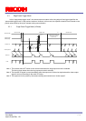
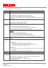
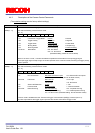
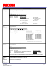
28H:
DLY[70]
29H
DLY[15...8]
[Delay time for the trigger] Initial Data: DLY[70] = 0, Data Range: 0 to 65,535
Sets the delay time from the trigger input signal to the start of the exposure.
At 15.3 fps: Delay time (us) = 74 x 0.0271606 * DLY[70] = 2.0099 (us) * DLY[70],
At 7.6 fps: Delay time (us) = 74 x 0.0407408 * DLY[70] = 4.0198 (us) * DLY[70],
At 3.8 fps: Delay time (us) = 74 x 0.0814816 * DLY[70] = 8.03952 (us) * DLY[70],
where CLK = pixel clock.
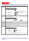
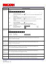
30H
PGA[70]
[CDS gain] Initial Data: PGA[70] = 0, data range: 0 to 255
Sets the CDS gain (programmable analog gain).
CDS gain (dB) = ( (PGA[7..0] + GOFS[7..0] ) * 2 * 0.0351) + 6
*GOFS[7...0]: The gain offset (The value of the address 32H)
31H
DGB[70]
[Digital gain] Initial Data: The factory adjusted value, data Range: 0 to 255
Output level = (input level - CLAMP[70]) * (1 + DGB[7..0] / 128) + clamp level
*CLAMP[7...0]: clamp level (The value of the address 38H)
32H
GOFS[70]
[Gain offset] Initial Data: The factory adjusted value, data range: 0 to 255
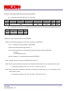
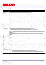
38H:
CLAMP[70]
[Clamp level] Initial Data: CLAMP[70] = 9, Data Range: 0 to 255
This sets the clamp level value of the black level.
At 12-bit output: Clamp level = CLAMP[70] x 8 + 56
At 10 bit output: Clamp level = (CLAMP[7...0] x 8 + 56) / 4
At 8-bit output: Clamp level = (CLAMP[7...0] x 8 + 56) / 16
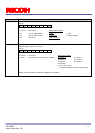
3EH: TP0[70]
3FH:TP0[98]
[Test pattern level] Initial data: 768 (300H), data range: 0 to 1023
Sets the output level of the test pattern 4: Raster (variable level) in 10-bit output format.
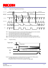
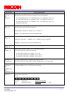
54H:
STRBDLY[7..0]
55H:
STRBDLY[15..8]
56H:
STRBDLY[23..16]
[Delay time (us) for the strobe signal]
Initial data: STRBDLY[23..0] = 0, data range: 0 to 2,000,000
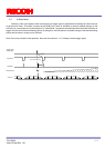
58H:
STRBPOL[7..0]
[Strobe signal polarity] Initial data: IOSIGNAL_POL[7..0] = 00H,
Sets the strobe signal polarity.
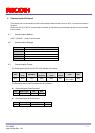
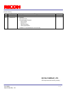
D[7..0]
D7 D6 D5 D4 D3 D2 D1 D0
D7 to D1 No Function Always set as “0000000”
D0: Strobe signal polarity 0: Non-invert
1: Invert