11
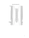
Regardless of if your cable ends up being longer or shorter than 3 meters,
all cable wires must be of equal length due to the extremely sensitive
timing characters of the Frame Grabber and Digital Camera interface.
The PXD Configuration Application
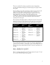
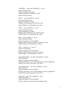
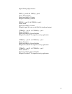
Imagenation provides a program called PXD Configuration Application which
is used to create a configuration file for your digital camera. The following
described each box in configuration application
Setting the camera Information (Select Camera Information Tab)
a) Pixel Type (also known as bit depth)
i. Y8, Y10, Y12, RGB32
b) Camera Type
i. Area Scan
ii. Line Scan or TDI
Image Geometry (Select Image Geometry Tab)
a) Image Size (Set resolution for camera used)
i. Width (in pixels)
ii. Height (in pixels)
b) Image format (set appropriately for camera used)
i. First button is for single channel, non-interlaced camera
ii. Second button for single channel, interlaced camera
iii. Next Three buttons are for 2-Channel cameras.
iv. Next Three buttons are for 4-Channel cameras.
v. The Custom button allows you to define a new format.
Exposure Timing (Select Exposure Timing Tab)
a) Exposure control Type
i. Async for cameras that generate frames that are occasionally
controlled by something other than the frame grabber. For example
this setting can be used to generate a frame only when it is
triggered by some external mechanism (snap-shot mode).
ii. Free run for cameras that output continuous frames of video based
on internal timing or synched to the drive signals from the grabber.
(Live video mode)
iii. Strobes to set the frame grabber to generate strobe signals at the
strobe0 and strobe1 pins. This can be used to program the exposure
or integration time or used as a general-purpose output signal or
strobe light.
b) Strobe 0 and Strobe 1.
i. This sets the polarity of the output to high true or low true.
c) Camera Control 0,1,2
i. This sets the polarity of the general-purpose control pins High true
or Low true.


