18
Pixel Swizzling
The second aspect of multi-channel cameras that can cause problems for digital
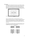
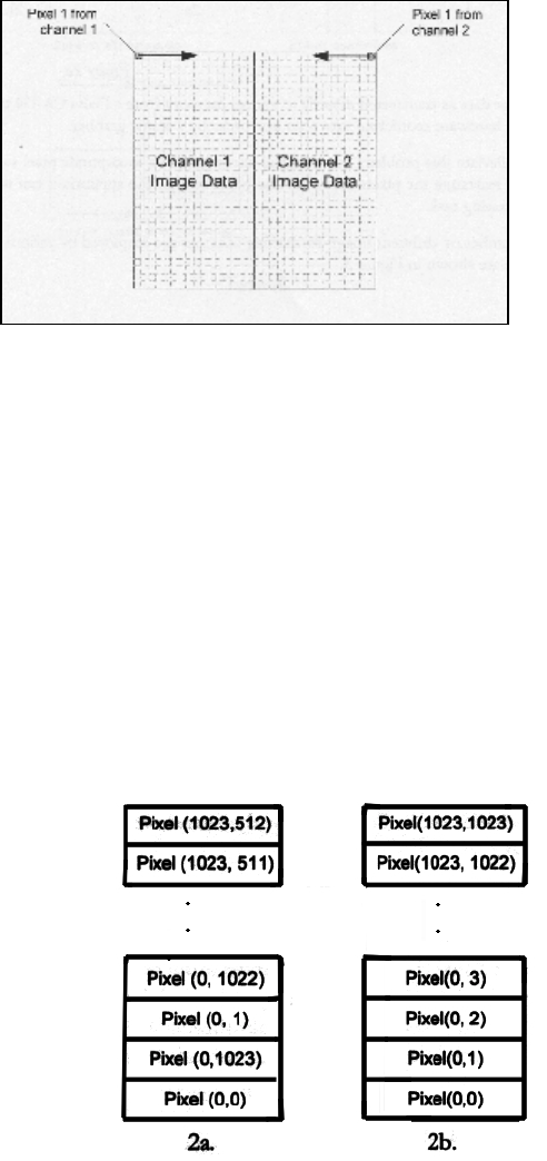
frame grabbers is the ordering of the received pixels. Figure 1 illustrates how the
Dalsa CA-D4 two-channel camera transmits pixels to the frame grabber. Two
pixels are received on the first pixel clock; pixel 0 from the top left edge of the
image and pixe1 1023 (remember there are 1024 pixels/line in the) from the top
right. On each successive clock the next pixel received from each channel is from
one step in toward the centerline.
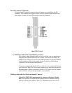
Figure 2.
Channel 1 in the Dalsa CA-D4 (in 2 channel mode) transmits image data
beginning at the left edge of the top row continuing to the midpoint at which time
it returns to the left edge to begin line two. It continues sending the data line by
line until it reaches the bottom of the image. Channel 2 transmits right to left,
stopping at the midpoint and in a similar fashion transmitting each half line from
top to bottom.
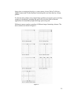
If this information were simply transferred to system memory (Figure3), the end-
user application would not have a coherent image but instead would need to de-
scramble the image software, a time consuming task.
Figure 3.


