20
A modern digital frame grabber should be able to convert data from cameras with
each of these formats into scan line ordered images in system memory.
Resolution
The ability of a camera to resolve details in a scene is dependent on the type of
lens employed and the relation of the camera to the scene. Therefore
manufacturers often describe the resolution of a camera by the stating number of
horizontal and vertical picture elements contained in the image sensor. For
example, the Pulnix TM1300 area-scan digital camera has 1300 picture elements
in each row by 1030 rows.
Scatter/Gather
Traditionally to get a contiguous block of memory in Windows 95 you had to use
a kernel level driver to capture the memory at power-on boot time. When your
application was done the memory couldn't be used by other applications until the
computer was rebooted without the contiguous block memory request.
On the other hand, requesting contiguous memory in an application at run-time
allows the memory to be freed up to other applications when the requestor is
finished. But large contiguous blocks of memory might not be available at run-
time because as a computer opens and closes applications the memory gets
fragmented into smaller blocks.
A frame grabber that supports scatter/ gather uses small blocks of memory as if it
has a large contiguous block. It does this by building a table of addresses of the
small blocks and stepping through the table to fill them with the completed
image, so that it appears to the application as one large block.
Troubleshooting
Symptom:
Black Screen Where Image Should Be
Possible Cause/Solution:
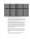
• Verify that the data lines and at a minimum the HDV, LDV, and CAMCLK (Pixel
Clock) are connected correctly on the cable. If the Camera is providing the Pixel
Clock (most common) then the CAMCLK (pins 65 & 15) will be used. If the
Frame grabber is providing the Pixel Clock, then the Synthclk (pins 57 & 7) will
be used.
• Verify that the power is properly connected to the camera. If the camera is being
powered off the board, then make sure the power pins are connected in the cable
and that the 12 volt floppy power connector is connected to the J1 connector on
the PCD1000.


