


4
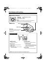
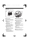
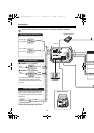
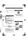
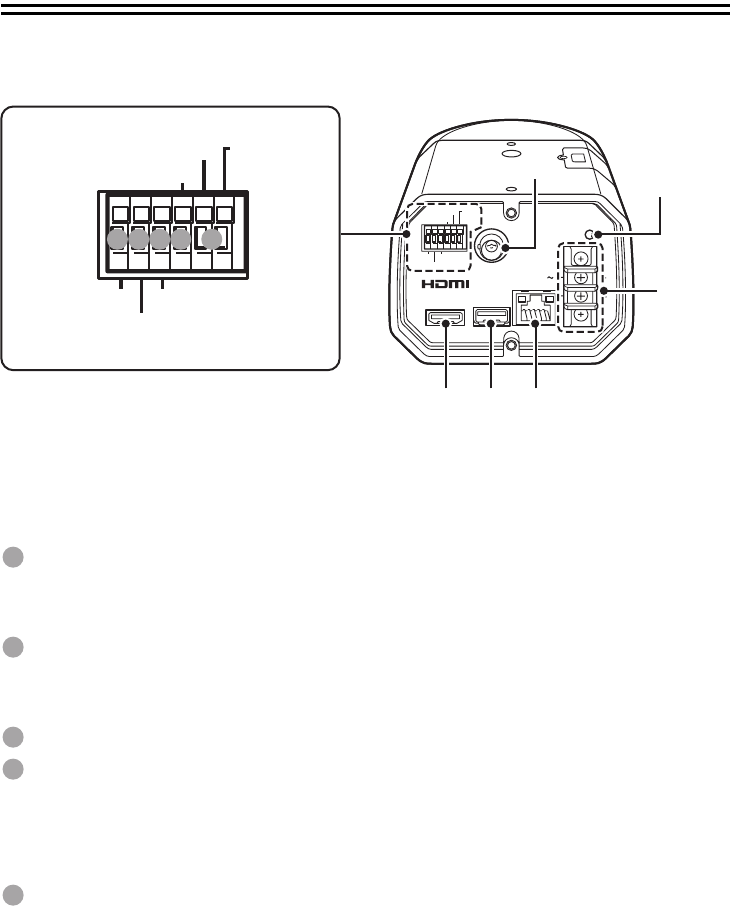
■Rear Face
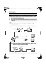
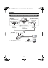
& For connections, see pages 11 and 12.
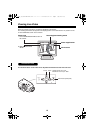
1Control terminals
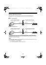
When connecting the cable, press and hold
down the protrusion of the terminal, insert the
cable into the terminal, and then release the
protrusion.
ZOOM terminal
Used to zoom in/out by connecting an
external switch.
• DC ±(6-12V), +: WIDE, –: TELE
FOCUS terminal
Used to perform the focus adjustment
remotely by connecting an external switch.
• DC ±(6-12V), +: FAR, –: NEAR
COM terminal (Earth terminal)
ALARM OUT terminal
Used to connect to an external buzzer or
lamp.
When an alarm is detected, the device
connected to the terminal notifies that an
alarm is detected.
ALARM IN 1/2 terminal
Used to connect an external alarm switch,
infrared sensor, or other device.
It can also be used as a switching terminal
for color and black/white video modes.
2SD OUT connector (BNC type)
Outputs SD (Standard Definition) video.
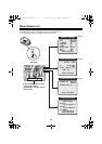
3AC24V / DC12V terminals
Connect this terminal to the power supply.
• When the camera is turned on, the
POWER lamp lights.
4LAN connector (RJ-45)
Used to connect the camera to your network.
5EX-HDD connector
Connects this connector to the external hard
disk case (VA-HDC4000) dedicated to use
with this camera.
For details, see the manual for the hard disk
case.
6HDMI connector
Outputs HD (High Definition) video. Connect
this connector to an HD video device.
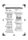
MEMO:
Select the SD OUT or HDMI terminal in on the
TV OUT SETTING screen via the network.
ALARM IN 1 ALARM
IN 2
ALARM OUT
ZOOM
FOCUS
POWER
AC24V
GND
DC
12V
COM
SD
OUT
EX-HDD
LAN
456
3
ALARM IN 1 ALARM
IN 2
ALARM OUT
ZOOM
FOCUS
COM
1
A B C D E
2
POWER
lamp
A
B
C
D
E
L5CL2_XE_US(INSTRUCTION).book 4 ページ 2008年8月25日 月曜日 午後3時43分