


2
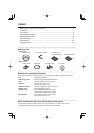
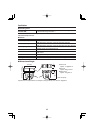
Name and Function of Each Component
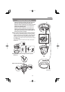
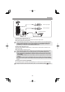
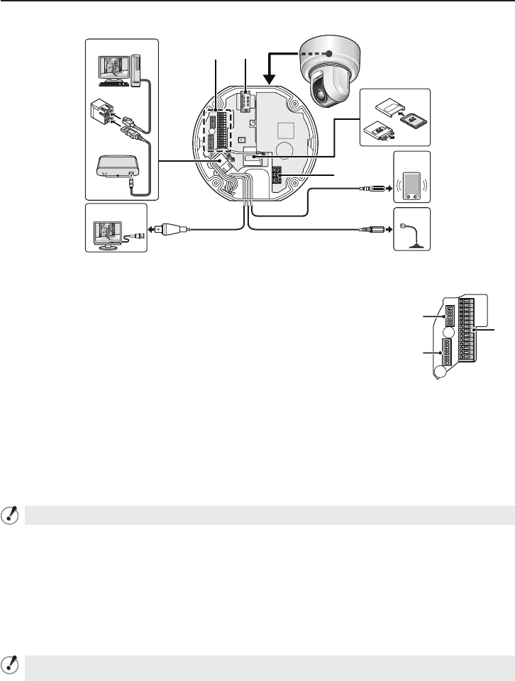
This device is composed of a camera unit and power unit (VA-94S).
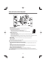
Connection Point
This is the connection point between the camera unit and the power unit.
Interface Board (accessories)
Control switch (transmission rate and protocol setting, etc.)
Address switch (control camera address setting)
Control terminal (connection of controller and alarm input/output cable)
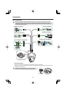
LAN/EX-HDD Terminal
LAN terminal (RJ-45 type):
Use this socket to connect the camera to your PC to enable network operation.
EX-HDD terminal (USB type):
When recording live video onto an external hard disk, put the hard disk in a dedicated hard disk
case (VA-HDC4000; sold separately) and then connect the case to the camera.
SD Card Slot
When recording live video onto an SD memory card, insert the card into the slot.
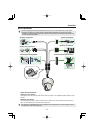
Power terminal
Use this cable to connect a 24 VAC power supply.
There is no power indicator on the camera.
Audio output terminal (black: 3.5-mm mini jack)
Connect this jack via an audio cable to the audio input jack of an amplified speaker system or the
monitor.
Audio input terminal (white: 3.5-mm mini jack)
Use this jack to connect an external microphone to listen to the sound while monitoring the live
video, or simultaneously record the video and sound.
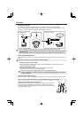
Monitor output terminal (BNC type)
This terminal is used for video output. Connect this terminal to a monitor, etc.
By installing an HDMI option board (VA-HDB90; sold separately), the camera can be connected to a
high vision monitor.