


8
OUT2
OUT1
C
IN8
IN7
IN6
IN5
IN4
IN3
IN2
IN1
COM
485B
485A
WH
B
L
S
L
O
R
B
R
B
K
Y
L
R
D
G
R
L
L
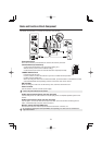
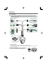
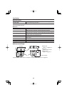
OUT1/2
IN 1-8
COM
COM
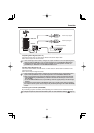
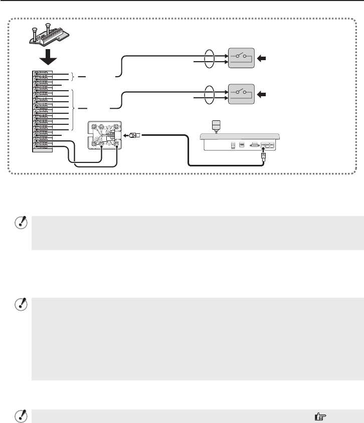
Alarm output signal
Alarm input signal
Controller connection
White Yellow
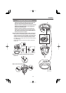
Outputting Alarm Signals (OUT 1-2)
Connect a buzzer, lamp, or other alarm device to the alarm output cable.
Alarm can be output via two channels.
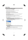
After connecting an alarm device, configure the output conditions for the corresponding alarm
output terminal (ALARM OUT1 or 2) via network operation on the ALARM SETTINGS screen.
Configuration of alarm output terminal is also possible via remote operation. For that, set
[ALARM OUT] to “REMOTE” on the ALARM SETTINGS screen.
•
•
Inputting Alarm Signals (IN 1-8)
Connect an alarm switch, infrared sensor, or other device to detect alarm conditions to the
alarm input cable.
Alarm can be input via eight channels.
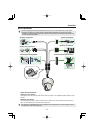
After connecting an alarm device, configure the input conditions for the corresponding alarm
input terminal (ALARM IN1 or 2) via network operation on the ALARM SETTINGS screen.
When using the alarm input terminal for day/night switching, configure the following settings.
•
Under [DAY/NIGHT], set [DAY/NIGHT] to “COLOR” and select the terminal you want to use in
[EXT ALARM].
•
On the ALARM SETTINGS screen, in [POLARITY], select the signal polarity of the alarm input
terminal.
Connecting an external switch to ALARM IN1 allows you to set the system clock by operating
the switch. To set the system clock, configure the [CLOCK IN] setting on the CLOCK SETTINGS
screen.
•
•
•
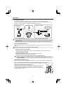
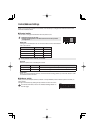
Connecting the Controller (485A/485B)
By connecting a system controller (sold separately), the camera can be controlled remotely.
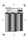
Configure the protocol, baud rate and address. (Refer to “Control/Address Settings” Page 9.)
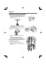
Connections