


Series 900 Single & Dual Instruction Manual
Page 9
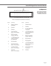
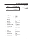
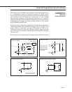
APPENDIX B
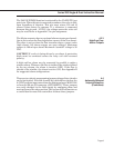
Back Panel Connector
Pin Assignments; 20-Pin
Transducer Connector
KEY
▼
(View of connector from back of enclosure)
PIN NO. FUNCTION PIN NO. FUNCTION
A Setpoint Output to 1 Chassis Ground
Controllers
2 Common
B Common
3 0-5 Volt Signal from
C Common Transducer
D Valve Test Point 4 +15 VDC Supply from
(Avail. I/O Connector) System Electronics to
Transducers
E RED Connection
(Factory Use Only) 5 BLACK Connection
(Factory Use Only)
F –15 VDC supply from
System Electronics 6 No Connection
to Transducers
7 No Connection
G No Connection
8 +15 VDC Supply from
H High Alarm Output System Electronics to
(Avail. I/O Connector) Transducers
I Low Alarm Output 9 4-20 mA Signal from
(Avail. I/O Connector) Transducer
J Valve Off 10 Common
(Avail. I/O Connector)
ABCDE FGH I J
••••••••••
••••••••••
12345678910