


Series 900 Single & Dual Instruction Manual
Page 11
The alarms are a normally, open collector transistor outputs; that
is, a transistor is used as a switch to ground. A “High” alarm
means that if the flow signal is higher than the alarm trip setting,
the transistor will be turned on. Conversely, a “Low” alarm
activates the transistor when the flow signal is lower than the
alarm trip setting. Sierra products usually incorporate a means of
configuring the output as either a high alarm or low alarm.
System Boxes contain both.
It is necessary to limit the current flow through the transistor to
100 mA maximum. The Standoff Voltage is set at 30 VDC. This
means that the transistor can safely withstand 30 VDC on it’s
collector while in the off state. Voltages greater than this may
cause failure of the transistor. (See Section 3.4 for specific instructhe
alarm levels.)
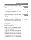
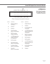
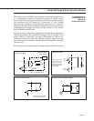
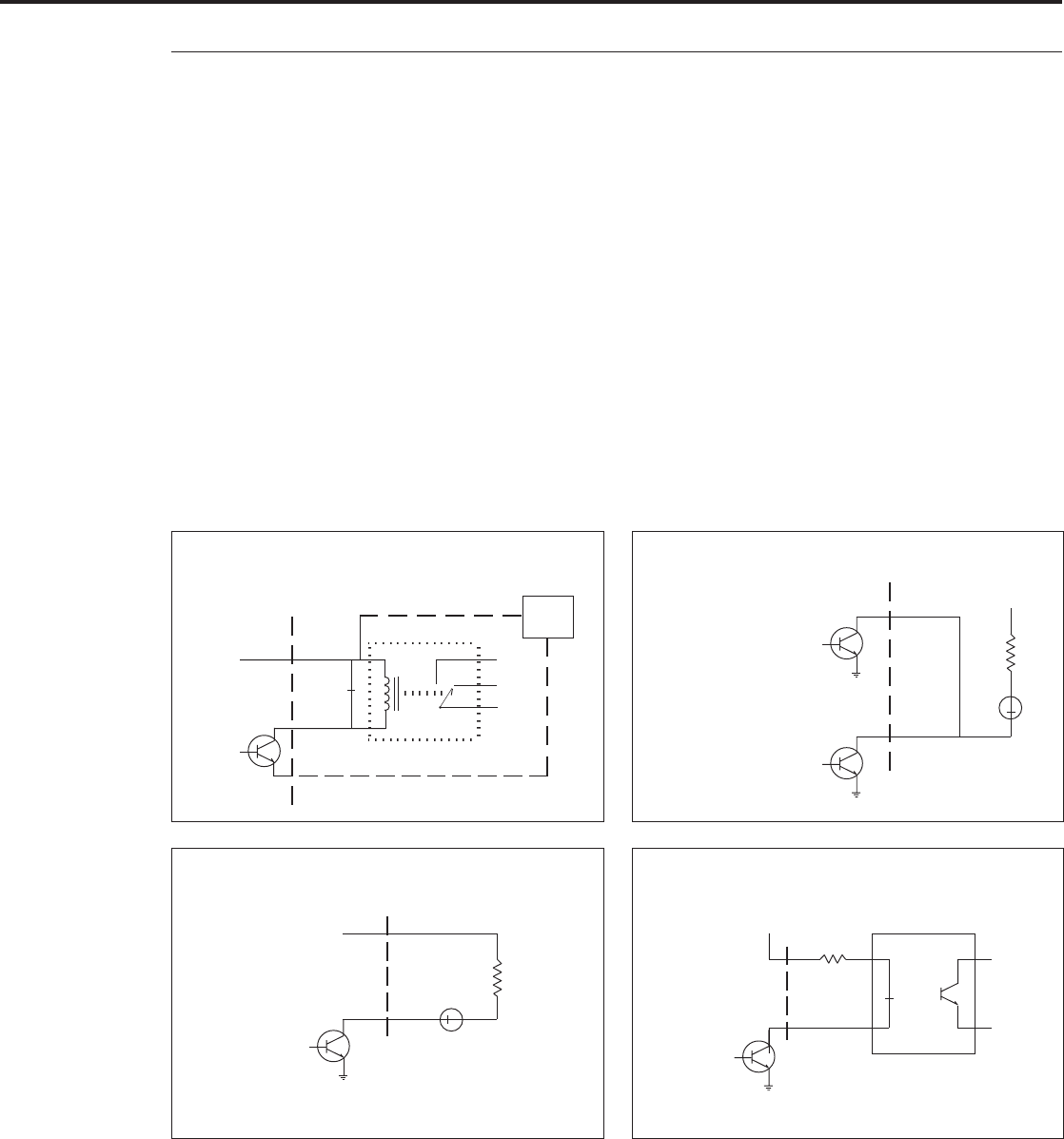
Following are several examples of commonly used alarm circuits:
APPENDIX D
Alarms for
System Electronics
Simple Indicator Light
Note: See IM for Back Panel
Connection & Pin Numbers.
+15
1K
▲
LED
▼
•
•
≈
Optional External
Power Supply
+15
+15
+15
common
NO
NC
COM
100mA ▲
MAX
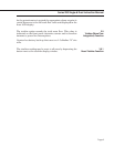
Alarm “on” actuates relay
PS
°
Alarm
Out
• •
Relay Interface
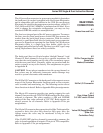
Isolated Open Collector Output
•
•
▲
MOC8020
+15
▼
≈
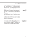
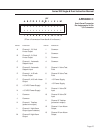
“Window” Alarm
1K
+15
▼
•
•
•
LED
▲
High
Alarm
Low
Alarm
≈
Alarm output: LED
will light if either high
or low alarm is acti-
vated to indicate flow
is outside preset high
and low limits.