


Series 900 Single & Dual Instruction Manual
Page 6
The VALVE PURGE function is activated by the VALVE TP (test
point) pin. When this pin is connected to common, the valve is fully
open regardless of setpoint. This pin must source 150 mA of
current when driven to common. If a voltmeter is connected
between this pin and –15 VDC, the voltage across the valve coil
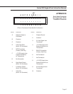
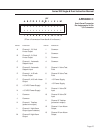
may be read. Refer to Appendix C for pin assignment.
The 26-pin connector has two optional alarm outputs per channel.
One is active when the flow drops below a preset value (low alarm).
The other is active when the flow increases above a preset value
(high alarm). All alarm outputs are open collector. Maximum
current is 100 mA per alarm. Maximum “standoff” voltage is 30
VDC.
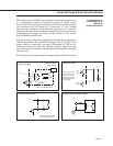
CAUTION! If a relay is being driven by an alarm, A protection
diode must be connected across the relay coil with reversed
polarity.
A high and low alarm may be connected in parallel to make a
window alarm. Whenever the flow is inside of the window defined
by the two alarms, the alarm is inactive (OFF). If the flow is
outside of the window, the alarm is active (ON). See Appendix D
for suggested alarm configurations.
There are two plastic programming jumpers plugged into a header
on the back panel. For each channel they determine whether the
0-5 VDC setpoint input comes from the front panel pots (MANUAL)
or from the 26-pin I/O connector (AUTOMATIC). These jumpers
are easily changed in the field simply by unpluging them and
moving them to the other position. The system will not function as
a control box for mass flow controllers without these jumpers.
4.3.3
High/Low Flow
Alarm Outputs
4.4
Automatic/Manual
Setpoint Selection
(Controllers)