


Series 900 Single & Dual Instruction Manual
Page 5
The AC power line connector (or power entry module) is located on
the back panel. A cordset is supplied with the System Electronics
and is compatible with wall outlets in the USA. Be sure System
Electronics is wired for the proper power mains voltage, either 115
VAC, 60 Hz or 230 VAC, 50/60 Hz, as indicated on the label. If you
wish to change the receptacle configuration, you may use any
standard CEEE 22 cordset to accomplish this.
The fuse is an integral part of the AC power connector. To remove
the fuse, turn the front panel power switch OFF then remove the
cordset from the back panel power connector. With the cordset
removed, a small door built into the back panel power connector
can now be flipped out exposing the fuse holder. In USA System
Electronics there is a single gray fuse holder which can be
unclipped and pulled out by hand. The fuse is an AGC type 3 amp
rating. Replacement fuses are widely available.
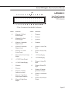
The back panel has two 20-pin headers labeled Channel 1 and
Channel 2. Each channel is set-up for a specific transducer. Be
sure that the serial number on the side of the transducer agrees
with the rear panel label. Normally, cables are prewired and the
entire system is set-up at the factory. Pin assignments are given
in Appendix B.
CAUTION! Do not plug a transducer into the wrong channel, as
flow values may be extremely inaccurate and/or damage may
result to system electronics and transducer.
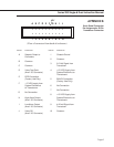
The 26-Pin I/O Connector on the back panel is the means to access
many of the System Electronics functions such as flow outputs,
valve override and monitoring, etc. The following section covers
these functions in detail. Refer to Appendix B for pin assignments.
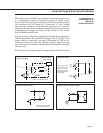
The 26-pin I/O connector provides two analog outputs for each
channel. One provides a 0-5 VDC LINEAR analog of the flow value
referred to common. The other supplies a 4-20 mA LINEAR
analog of the flow value referred to +15 VDC. Both outputs are
always present for all channels. Refer to Appendix B for pin
assignments.
The 26-pin I/O connector has connections for Side-Trak controller
systems to drive the valve fully closed or fully open. Also, the
voltage across the valve may be monitored to help in valve
adjustment.
If the VALVE OFF pin for a channel is connected to common, the
valve is closed regardless of setpoint. This pin is TTL compatible.
Refer to Appendix C for pin assignments.
4
REAR PANEL
CONNECTIONS
4.1
Power Line and Fuse
4.2
20-Pin Connectors for
Sierra Flow
Meters/Controllers
4.3
26-Pin I/O Connector
4.3.1
Flow Value Output
0-5 VDC and 4-20 mA
4.3.2
Valve Off/Purge/Monitor
(Side-Trak
Controllers Only)