


Series 900 Single & Dual Instruction Manual
Page 3
System Electronics’s front panel controls provide ease of opera-
tion. To get the most benefit from a Sierra Instruments, Inc.
System Electronics, read these instructions before attempting
operation.
On dual channel units, the rotary switch labeled Channel Select
determines which channel is displayed.
The flow value is normally read from the LCD Display. Readout
is usually in engineering units and is indicated on the label.
System Electronics toggles between flow reading and flow setpoint
by the switch labeled “SET/READ”. When in the READ mode, the
display shows flow value as above. When in the SET mode, the
display shows the current setpoint value in the same units as the
“READ” mode.
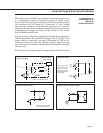
For each channel, there is an optional high alarm and/or low
alarm. Each alarm output is active whenever the flow is above or
below the preset value, respectively. All alarm outputs are OPEN
COLLECTOR NPN and sink current to COMMON. If driving a
relay, a reverse polarity protection diode must be connected across
the coil. See appendix D for additional information regarding the
alarms.
When the flow is below the low alarm set value, the low alarm is
active. (Alarm is ON).
When the flow value is greater than the high alarm set value, the
high alarm is active. (Alarm is ON).
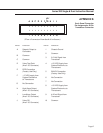
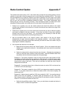
The alarm adjustments are located internally. The front bezel
must first be removed by unscrewing the four black screws
holding it in place, then sliding the top cover out to expose the
main printed circuit board. See the drawing in Appendix G giving
the location of the alarm component.
The alarm display is activated using internal switches. These
switches are located near the front panel. The switch labeled ALM
or NORM shows the alarm setting on the front panel display. The
toggle switch labeled HI/LO selects whether the high or low alarm
is displayed. This switch must be held at the ALM position while
adjusting the alarm point with the switch in the ALM position, the
LCD display will show the alarm value.
The alarm adjustment potentiometers are located toward the rear
of the main PCB. As you face the front of the unit, Channel 1 is on
the right and Channel 2 is on the left. The high alarm pots are
marked R29 and the low alarm pots are marked R33.
3.2
Reading Flow Value
3
FRONT PANEL
FUNCTIONS
3.1
Channel Selection
3.3
Flow Setpoint Display
and Adjustment
(Controllers Only)
3.4
High/Low Alarm Display
and Adjustment