• Get Basic Results .vi
These VIs are easy to understand if one has some experience in LabVIEW programming. The
processing sequence is controlled by the “Error In” and “Error Out” connection chain. That
means a function unit is processed earlier if it is closer to the starting “Error In” connection.
In other words, we use the “Error Out” to “Error In” connection sequence to link each
operation in the process. Since the results interface should be always active unless users
terminate the process, we have used a “while-loop” to keep it active.
B.3.2 Beam Viewer .vi
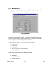
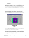
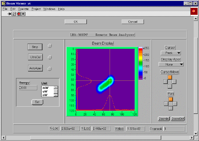
This program allows you to control cursor and pan and zoom as well as basic operations. As
in the previous example, Beam Viewer .vi utilizes some of the same SubVI’s already
discussed, while introducing image data transfers and a local display VI. However the design
method is the same. We use SubVIs to manipulate each function, then link them together.
Beam Viewer Panel
Figure 65
In order to display intensity graphics, we used LabVIEW’s “Attribute Note” feature to handle
the size and palette, etc. Another LabVIEW tool we used to share data is “Local Variables”.
This allows you to use any variable value anywhere in a diagram.
Let us go through each major process step in the Beam Viewer .vi diagram. Before the while-
loop, we enable frame Service Request and get Palette (if you want to change the palette,
you should include get palette inside of this while-loop). Then:
1. Check if each of the Run/Stop, UltraCal, and AutoAperture buttons is on or off.
2. Check if Set energy/unit button has been clicked.
Operator’s Manual LBA-PC
Doc. No. 10654-001, Rev 4.10
273


