


10
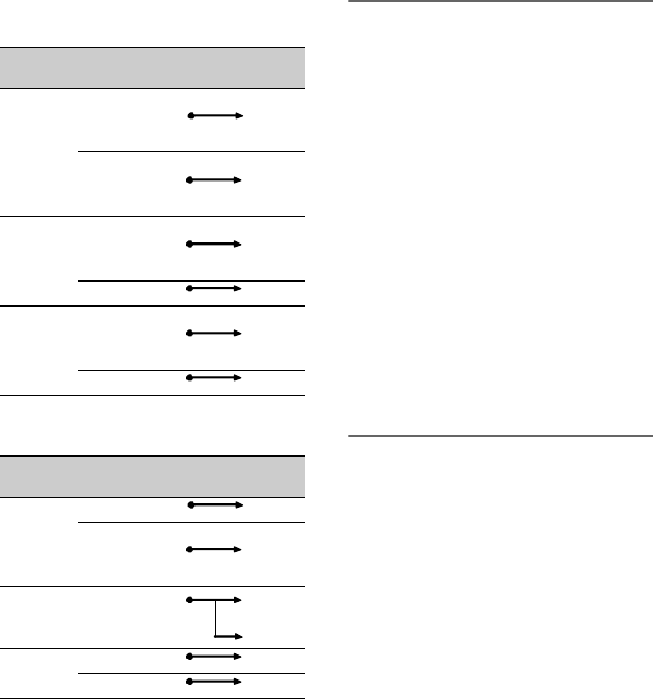
When the CH1 switch is set to
INT MIC
When the CH1 is set to INPUT1
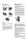
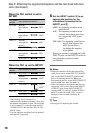
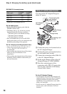
6 Set the INPUT1 switch H to an
appropriate position for the
microphone connected to the
INPUT1 jack D.
LINE: For inputting sound from an
audio device
MIC: For inputting sound from an
external microphone that does
not support the +48V power
source.
MIC+48V: For inputting sound from a
device that supports the
+48V power source
including the supplied
microphone.
When you connect a microphone to the
INPUT2 jack, set the INPUT2 switch to
an appropriate position for that
microphone.
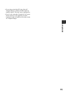
b Notes
• When you connect a device that supports the
+48V power source to the INPUT1 or INPUT2
jack, set the INPUT1/INPUT2 switch to MIC
prior to connecting the device. When you
disconnect the device, set the INPUT1/INPUT2
switch to MIC first, then disconnect it.
• When you connect a microphone that does not
support the +48V power source to the INPUT1
or INPUT2 jack, set the INPUT1/INPUT2
switch to MIC. If you use it with the INPUT1/
INPUT2 switch set to MIC+48V, it may be
damaged or the recorded sound may be
distorted.
z Tips
• See page 42 for adjusting the volume.
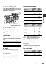
CH2 switch
position
Input channel and source
INT MIC Internal
microphone
(L)
CH1
Internal
microphone
(R)
CH2*
INPUT1 Internal
microphone
(mono)
CH1
XLR INPUT1 CH2**
INPUT2 Internal
microphone
(mono)
CH1
XLR INPUT2 CH2**
CH2 switch
position
Input channel and source
INT MIC XLR INPUT1 CH1
Internal
microphone
(mono)
CH2**
INPUT1 XLR INPUT1 CH1
CH2**
INPUT2 XLR INPUT1 CH1
XLR INPUT2 CH2**
* The recording level of channel 2 is
synchronized with that of channel 1 when only
the internal microphone is used. The recording
level of channel 2 is controlled with the CH1
(AUDIO LEVEL) dial and the CH1 (AUTO/
MAN) switch.
**You can adjust the recording levels of channel 1
and channel 2 separately.
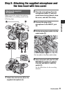
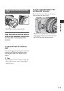
Step 2: Attaching the supplied microphone and the lens hood with lens
cover (Continued)