


18
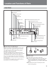
Location and Functions of Parts
Not lit: The unit is not in digital transmission mode
(factory default setting).
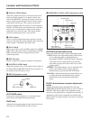
qd AUTO IRIS button
Selects the iris adjustment mode. Before using this
button, set the IRIS switch on the camera/camcorder to
AUTO.
OFF (not lit): Manual adjustments can be made with
the IRIS knob.
ON (lit): The iris is adjusted automatically.
qf IRIS knob
When the AUTO IRIS button is off, adjust the camera/
camcorder lens iris by rotating this knob. When the
button is on, the iris is adjusted automatically.
qg MASTER BLACK knob
Adjusts the video signal black level.
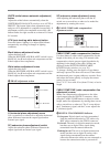
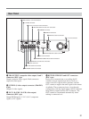
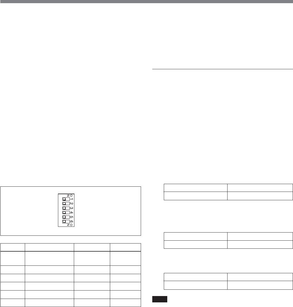
qh System setting switches
Set the following items. Power this unit off before
setting switches.
Switch 1: CCU command mode
OFF: Use CCU-M5A system commands (M5A
mode). This unit can be used to carry out similar
control operations to those available with the
CCU-M5A/M5AP.
ON: Use CCU-TX7 system commands (TX7 mode).
Select ON (TX7 mode) when this unit is used with
CA-D50. The RCP-TX7 (not available in EU
countries) can be used in TX7 mode.
Set to off (M5A mode) when this unit is connected to a
DSR-370/370P/570WS/570WSP or when this unit is
connected to a camera via a CA-537/537P.
Switch 2: Return signal mode
OFF: Transmit color as the return signal.
ON: Transmit B/W as the return signal.
Prompter signals cannot be transmitted when color is
selected. Select B/W when using prompter signals.
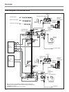
Switch 3: Digital transmission
ON: Selects digital transmission between this unit
and the camera adaptor.
OFF: Selects analog transmission between this unit
and the camera adaptor.
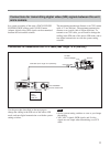
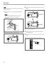
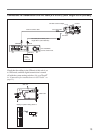
For digital transmission, cabling must be changed in
the SDI unit of this unit.
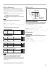
Switches 4 and 5: Output mode 1 and output
mode 2
Select the type of analog signal output from this unit.
Y/R–Y/B–Y: Output Y, R–Y, and B–Y signals from
the Y/G/Y, R–Y/R/C, and B–Y/B OUTPUT
connectors. Set the switches as follows.
Nothing is output from the S VIDEO connector.
R/G/B: Output G, R, and B signals from the Y/G/Y,
R–Y/R/C, and B–Y/B OUTPUT connectors. Set
the switches as follows.
Nothing is output from the S VIDEO connector.
Y/C: Output S-video signals from the S VIDEO
OUTPUT connector. Set the switches as follows.
Note
When switch 3 (digital transmission) is on, the settings
of switches 4 and 5 are ignored and no signals are
output from any of the Y/G/Y, R–Y/R/C, and S
VIDEO connectors.
Switch
Switch 1
Switch 2
Switch 3
Switch 4
Switch 5
Switch 6
Item
CCU command
mode
Return signal mode
Digital transmission
Output mode 1
Output mode 2
Remote/local
OFF (default)
M5A mode
Color
OFF
Y/R–Y/B–Y
Y/R–Y/B–Y
Remote
ON
TX7 mode
B/W
ON
R/G/B
Y/C
Local
Switch 4 OFF
Switch 5 OFF
Switch 4 ON
Switch 5 – (ON/OFF both OK)
Switch 4 OFF
Switch 5 ON