


22
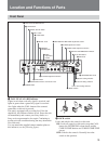
Location and Functions of Parts
Note
When using B/W return mode (see “qh System setting
switches” on page 18) and inputting a return video
signal to the RETURN VIDEO IN connector, always
input a reference sync signal to the GENLOCK IN
connector to synchronize the return video signal with
the sync signal. Failure to synchronize the return video
signal with a sync signal can cause camera/camcorder
synchronization to become unstable.
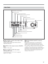
5 CAMERA connector (Z-type, 26-pin)
Connect a CCZ-An camera cable (not supplied) here to
connect this unit to devices such as a CA-D50 camera
adaptor on the camera.
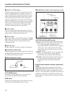
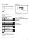
6 REMOTE connector (10-pin)
Using an CCA-7 connection cable (not supplied),
connect to an RM-M7G Remote Control Unit (not
supplied) or an RCP-TX7 (not supplied). The RCP-
TX7 is not available in EU countries.
7 SDI IN and OUT connectors
These are input and output connectors for digital video
(SDI) signals.
8 -AC IN connector
Connect to an AC power source using the supplied
power cord.
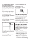
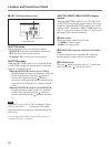
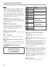
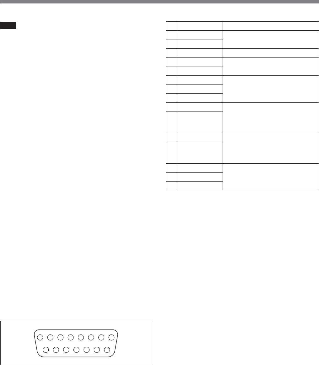
9 INTERCOM/TALLY/AUX connector (D-sub,
15-pin)
Inputs and outputs tally and intercom signals. Connect
to the tally/intercom connector of the intercom system.
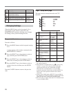
INTERCOM/TALLY/AUX connector pin
assignment
87654321
15 14 13 12 11 10 9
No. Signal name Description
1 AUX-RX (X) Contact your Sony dealer or a
9 AUX-TX (X)
Sony service representative.
2 AUX/TALLY (G) Gnd (AUX, tally)
q; G TALLY IN ON: Gnd
3 R TALLY IN OFF: Open
qa 4W (G) IN
4 4W (X) IN 4-wire talk, 0 dBu
a)
, balanced
qs 4W (Y) IN
5 2W (X) IN/OUT 2-wire, 0 dBu
a)
qd 2W (G) IN/OUT
Termination required
(recommended termination
impedance: 600 ohms)
6 RTS (G) IN/OUT 2-wire 0 dBu
a)
qf RTS (X) IN/OUT Termination required
(recommended termination
impedance: 200 ohms)
7 4W (Y) OUT
qg 4W (G) OUT 4-wire receive, 0 dBu
a)
, balanced
8 4W (X) OUT
a) 0 dBu = 0.775 Vrms
q; MIC OUT (microphone output) connector
(XLR, 3-pin)
Outputs microphone signals from the camera/
camcorder.
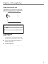
qa PROMPTER VIDEO IN and OUT connectors
(BNC type)
Input and output connectors for prompter signals. The
IN and OUT connectors have a loop-through
configuration, with the signal input to the IN connector
being directly output from the OUT connector. The
OUT connector is terminated automatically when
nothing is connected to it.
qs GENLOCK IN and OUT connectors (BNC type)
The IN connector accepts a reference video signal
(black burst or composite video) for external sync. The
IN and OUT connectors have a loop-through
configuration, with the signal input to the IN connector
being directly output from the OUT connector. The
OUT connector is terminated automatically when
nothing is connected to it.
qd Spare connector
This is a spare connector, not currently used.