


141
Additional information
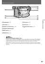
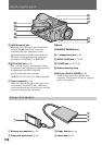
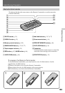
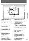
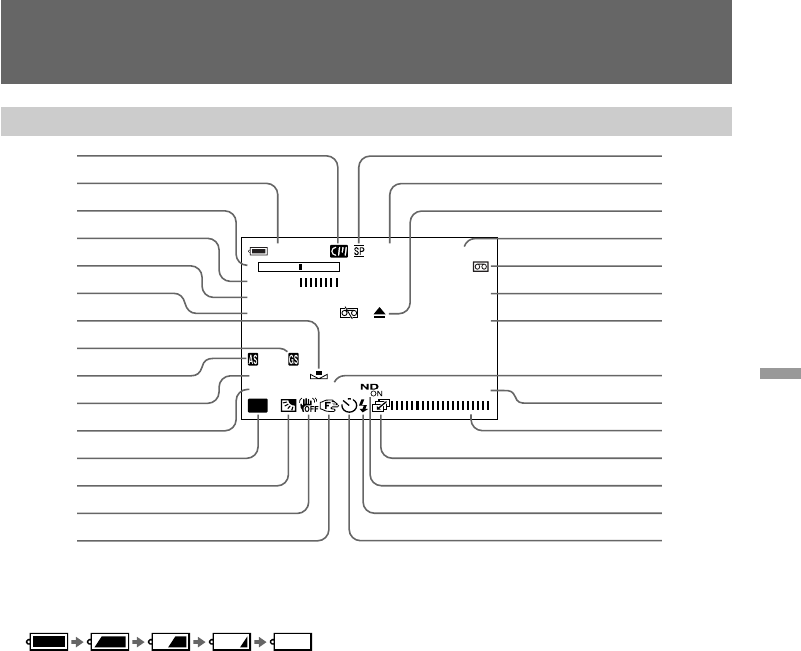
Identifying the parts
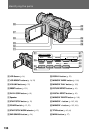
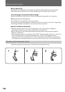
Operation indicators
!§ Recording mode indicator (p. 30)
!¶ Standby/Recording indicator (p. 12)/Tape
transport mode indicator (p. 22)/Image
quality mode indicator (p. 95)
!• Warning indicators (p. 143)
!ª Time code indicator (p. 13) /Self diagnosis
indicator (p. 132)/Image number indicator
(p. 106)
@º Remaining tape indicator (p. 142)/Memory
playback indicator (p. 106)
@¡ ZERO SET MEMORY indicator (p. 80)
@™ END SEARCH indicator (p. 24)
@£ Gain indicator (p. 81)
@¢ Audio mode indicator (p. 30)
@∞ Microphone level indicator (p. 48)
@§ Continuous mode indicator (p. 104)
@¶ ND filter indicator (p. 49)
@• Video flash ready indicator (p. 33)
@ª Self-timer indicator (p. 18)
1 Cassette memory indicator (p. 116)
2 Remaining battery indicator (p. 120)
3 Zoom indicator (p. 14) /Exposure indicator
(p. 44)/ Data file name indicator (p. 92)
4 Digital effect indicator (p. 42)
5 PROG.SCAN indicator (p. 35)/
16:9WIDE indicator (p. 39)
6 Picture effect indicator (p. 40)
7 White balance indicator (p. 46)
8 Gain shift indicator (p. 53)
9 AE shift indicator (p. 52)
0 Shutter speed indicator (p. 45)
!¡ Aperture indicator (p. 55)
!™ Program AE indicator (p. 54)
!£ Back light indicator (p. 38)
!¢ Steady shot OFF indicator (p. 51)
!∞ Manual focus/Infinity indicator (p. 57)
120min STBY 0:12:34
–+
12min
STI LL ZERO SET
PROG. SCAN MEMORY
NEG.ART END
SEARCH
.
–
3
10000
F1.6 12
dB
16BIT
A
AE
8
7
6
5
4
3
2
1
9
0
!¡
!™
!£
!¢
!∞
@£
@™
@¡
@º
!ª
!•
!¶
!§
@¢
@∞
@§
@¶
@•
@ª