38
Connecting the Remote Control Unit (DSR-450WS/450WSP only)
Chapter 2 Preparation
Function of the REC button when the
remote control unit is connected
You can select the function of the REC button on the
camcorder when the remote control unit is connected,
using the RM REC START item on the FUNCTION 3
page of the MAINTENANCE menu.
To disable the camcorder REC button and the
lens VTR button
On the FUNCTION 3 page of the MAINTENANCE
menu, set RM REC START to RM.
If the REC SWITCH function is assigned to the ASSIGN
switch, this setting also disables these controls.
To enable the camcorder REC button and the lens
VTR button
On the FUNCTION 3 page of the MAINTENANCE
menu, set RM REC START to CAM.
If the REC SWITCH function is assigned to the ASSIGN
switch, this setting also enables these controls. In this case,
the VTR button on the remote control unit is disabled.
To enable all of the camcorder REC button, the
lens VTR button, and the remote control unit VTR
button
On the FUNCTION 3 page of the MAINTENANCE
menu, set RM REC START to PARA.
If the REC SWITCH function is assigned to the ASSIGN
switch, this setting also enables these controls.
When the monitor is connected to the
remote control unit
The MONITOR connector (BNC type) of the RM-B150/
B750 outputs the same signal as that from the MONITOR
OUT connector on the camcorder.
Use the black cable supplied with the RM-B150/B750 to
connect the monitor to the MONITOR connector on the
RM-B150/B750.
When the remote control unit is
disconnected from the camcorder
The camcorder settings return to the settings in effect
before the remote control unit was connected.
By making a menu setting, the setting of the paint
adjustment made with the remote control unit can be
retained even after the remote control unit is removed from
the camcorder.
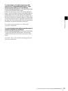
For details, see “To use settings of the paint adjustment
data stored in the “independent data region” even when a
remote control unit is connected” on page 39.
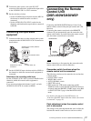
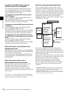
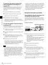
Structure of the paint adjustment data
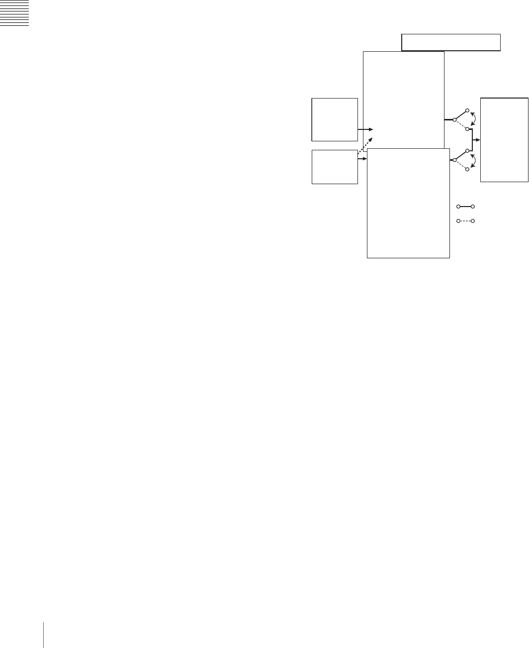
The non-volatile memory of the camcorder used for
storing paint adjustment data consists of two regions as
shown below: one is the “independent data region” that is
used when a remote control unit is not connected, and the
other is the “remote control data region” that is used when
a remote control unit is connected. Paint adjustment data is
automatically selected and output to the camcorder
depending on whether or not a remote control unit, such as
an RM-B150, is connected.
Thus, when a remote control unit is connected to the
camcorder, the effective data region is switched to the
“remote control data region” and the settings of the paint
adjustment that were in effect last time the remote control
unit was used are recalled.
Settings of the absolute value volume
1)
and absolute value
switches
2)
are overwritten by those on the remote control
unit after the remote control unit is connected.
When the remote control unit is removed from the
camcorder, the “independent data region” becomes
effective. Thus the camcorder will return to the settings
that were in effect before the remote control unit was
connected.
1) Absolute value volume: The data corresponding to the rotation degree
(position) of the volume knob is output. The data corresponding to the
rotation amount (change) is called the relative value volume.
2) Absolute value switch: Toggle switches or slide switches (except the
temporary switches) (or controls) whose positions must coincide with their
functions are called absolute value switches.
Non-volatile memory
Independent data
region
MASTER BLACK
MASTER GAMMA
KNEE POINT
DETAIL LEVEL
R/B GAIN
R/B BLACK
Remote control
data region
MASTER BLACK
MASTER GAMMA
KNEE POINT
DETAIL LEVEL
R/B GAIN
R/B BLACK
Setup
menu of the
camcorder
RM-B150
Hardware
of the
camera
RM-B150 connected
RM-B150 not
connected


