


11
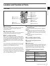
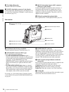
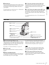
Location and Function of Parts
Chapter 1 Overview
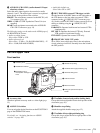
To ensure proper operation of the video light, Sony
recommends the use of the battery pack BP-GL65,
BP-GL95, or BP-L60S with the camcorder.
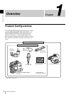
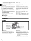
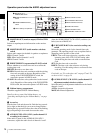
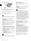
c OUTPUT /DCC (output signal/dynamic contrast
control) switch
Switches the video signal, which is output to the VTR part,
viewfinder, and video monitor from the camera part,
between the following two.
BARS: Outputs the color bar signal.
CAM: Outputs the video signal from the camera. When
this is selected, you can switch DCC
*
on and off.
* DCC (Dynamic Contrast Control): Against a very bright background
with the iris opening adjusted to the subject, objects in the background will
be lost in the glare. The DCC function will suppress the high intensity and
restore much of the lost detail and is particularly effective in the following
cases.
• Shooting people in the shade on a sunny day
• Shooting a subject indoors, against a background through a window
• Any high contrast scene
d GAIN switch
Switches the gain of the video amplifier to match the
lighting conditions during shooting. The gains
corresponding to the L, M, and H settings can be selected
in the menu. (The factory settings are L = 0 dB, M = 9 dB,
and H = 18 dB.)
When this switch is adjusted, the new setting appears on
the setting change/adjustment progress message display
area of the viewfinder screen for about 3 seconds.
For details, see “Setting gain values for the GAIN switch
positions” on page 103.
e POWER switch
Turns the main power supply on and off.
f MONITOR (monitor volume adjustment) knob
Controls the volume of the sound other than the warning
tone that is output via the built-in speaker or earphones.
Turning this knob to the minimum setting mutes the audio
output.
g ALARM (alarm tone volume adjustment) knob
Controls the volume of the warning tone that is output via
the built-in speaker or earphones. Turning this knob to the
minimum setting mutes the alarm tone.
h LCD monitor
Displays VTR-related warnings, remaining battery
capacity, remaining tape capacity, audio levels, time data,
and so on.
For details, see “Status display on the LCD monitor” on
page 23.
i MENU switch
When flicking toward ON, the USER menu is displayed.
When flicking toward STATUS, the status of the
camcorder (of current settings) is displayed.
For details, see “Displaying menus” on page 93.
j WHITE BAL (white balance memory) switch
Controls adjustment of the white balance.
PRST: Adjusts the color temperature to the preset value.
Use this setting when you have no time to adjust the
white balance.
A or B: When the AUTO W/B BAL switch (page 9) is
pushed to WHT, the white balance is automatically
adjusted according to the current position of the
FILTER selector
(page 9), and the adjusted value is
stored in either memory A or memory B. There are
two memories for each CC filter, allowing a total of
eight adjustments to be stored. When this switch is set
to A or B, the camcorder automatically adjusts itself
to the stored value corresponding to the current
settings of this switch and the FILTER selector.
You can use the AUTO W/B BAL switch even when
ATW
*
is in use.
B (ATW): When this switch is set to B and WHITE
SWITCH <B> is set to ATW on the FUNCTION 2
page of the OPERATION menu, ATW is activated.
When this switch is adjusted, the new setting appears
on the setting change/adjustment progress message
display area of the viewfinder screen for about 3
seconds. You can assign the ATW function to the
ASSIGN switch on the FUNCTION 1 page of the
OPERATION menu.
For details about how to assign the function to the ASSIGN
switches, see
“Assigning functions to ASSIGN switches”
on page 106.
* ATW (Auto Tracing White Balance): The white balance of the picture
being shot is adjusted automatically for varying lighting conditions.
Note
OUTPUT
DCC
CAMBARS
ONOFF
OUTPUT: BARS, DCC: OFF
A color bar signal is output and the DCC circuit does not
operate. Use this setting to adjust the video monitor, to
record the color bar signal, etc.
OUTPUT: CAM, DCC: OFF
The video signal from the camera is output, and
the DCC circuit does not operate.
OUTPUT: CAM, DCC: ON
The video signal from the camera is output, and
the DCC circuit operates.
ALARM
Minimum Maximum