Chapter 1 Overview
Chapter 1 Overview 35
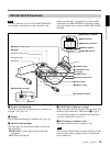
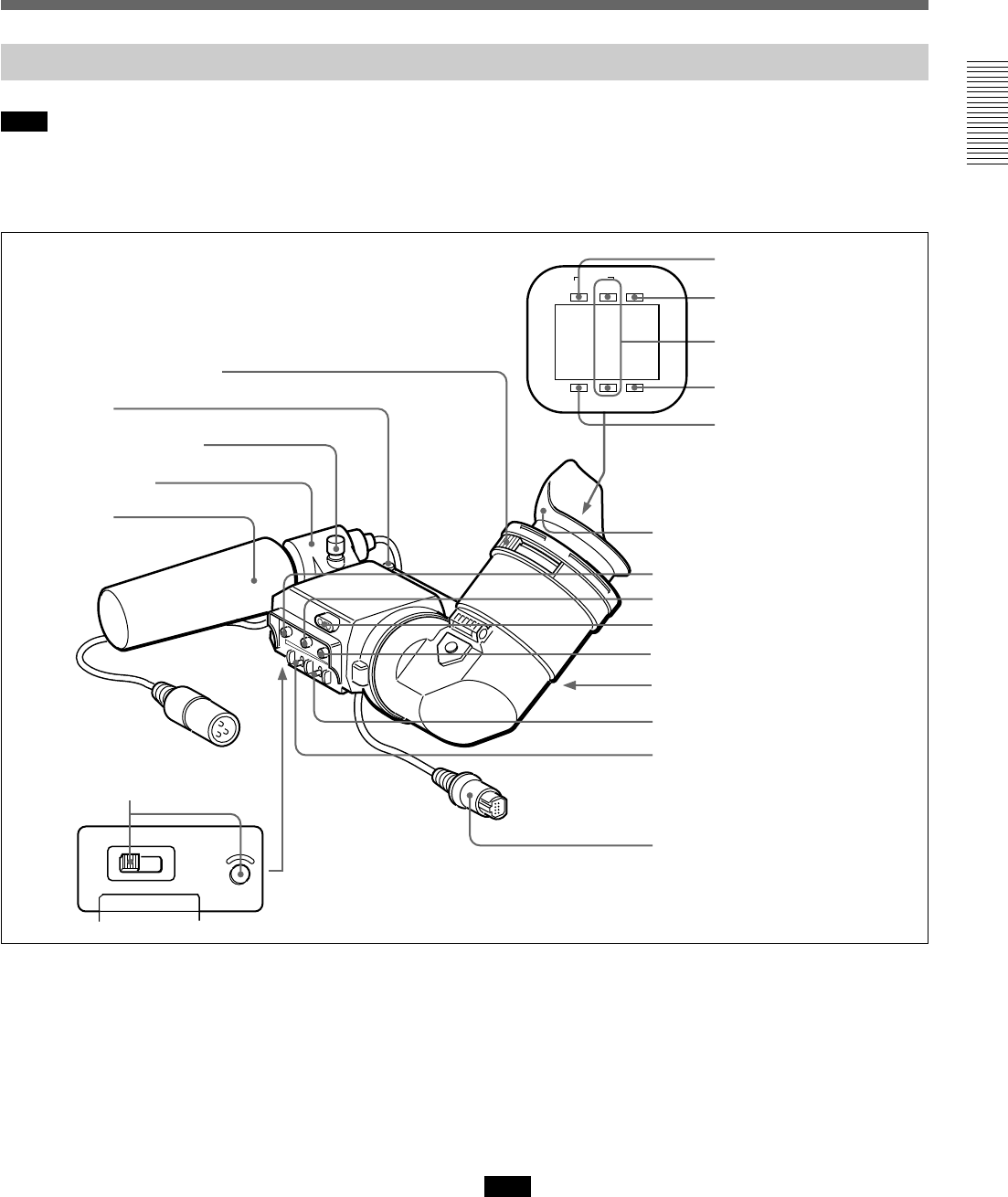
DXF-801/801CE Viewfinder
Note
You can switch the scan size of the DXF-801/801CE
in accordance with the aspect ratio selected on the
camera or camcorder. It operates in 4:3 mode when
connected to the DSR-390/390P. It operates in either
4:3 or 16:9 mode when connected to the DSR-570WS/
570WSP.
HIGH LOW OFF
LIGHT
SHUTTER GAIN UP
TAKE BATTREC
TALLY
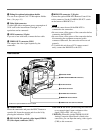
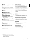
1 Eyepiece focusing knob
Turn this to adjust the viewfinder focus to match your
eyesight. (See page 132.)
2 Stopper
Lift up when detaching the viewfinder (See page 41).
3 LIGHT switch and light
The light lights the lens and the switch controls the
light as follows.
HIGH/LOW: Turn the light on and control the
brightness.
OFF: Turns the light off.
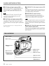
3 LIGHT switch and light
4 TAKE/TALLY indicator
5 BATT indicator
6 REC/TALLY indicators
7 GAIN UP indicator
8 SHUTTER indicator
9 PEAKING control
0 CONTRAST control
qa Tally lamp
qs BRIGHT control
qd Eyepiece release catch
qf TALLY switch
qg DISPLAY switch
qh Viewfinder connector
Eye cup
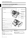
1 Eyepiece focusing knob
2 Stopper
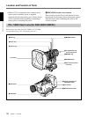
Microphone holding screw
Microphone holder
Microphone
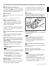
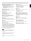
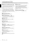
4 TAKE/TALLY indicator (orange)
When using the ClipLink function while shooting, this
indicator lights when the TAKE button (6 on page
15) has been pressed to set a Mark IN point and goes
out when a Mark OUT point is set.
5 BATT (battery) indicator (red)
This lights when the battery capacity is low.
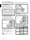
Note
This indicator flashes when switches and knobs on the
camera control unit are operated. This is normal and
not a malfunction.


