Chapter 4 Viewfinder Screen Indications and Menus 93
Chapter 4 Viewfinder Screen Indications and Menus
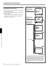
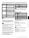
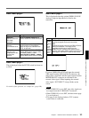
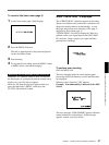
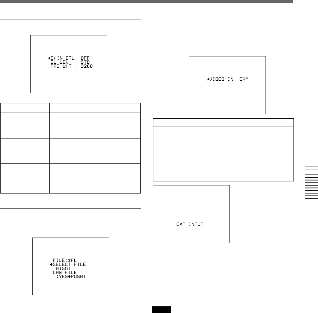
Basic menu page 2
Basic menu page 3
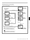
This is displayed when the SETUP switch has been set
to FILE.
For details of this operation, see “Setup Files” (page 108).
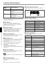
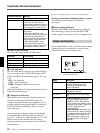
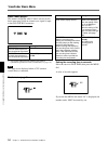
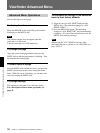
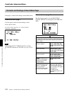
Basic menu page 4
This is displayed when the optional DSBK-501/501P
Analog Composite Input Board is fitted to the
camcorder.
If you set VIDEO IN to EXT and input the external
VBS signal from the GEN LOCK IN connector, the
image in the viewfinder and the signal output from the
MONITOR OUT connector are switched to the
external video signal. When inputting the external
video signal, “EXT INPUT” always blinks on the
screen.
Notes
•When VIDEO IN is set to EXT, the video signals are
not output from the S VIDEO OUT connector.
•When VIDEO IN is set to EXT, the basic menu page
5 is not displayed.
• This page is not displayed when a CCU (camera
control unit) is connected.
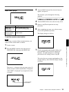
Item Settings
SKIN DTL
Sets the amount of
skin detail
correction.
0.0 to 0.5 (normal value) to 1.0
Smaller values set a softer skin detail.
LOW, STD (normal value), HIGH
Set the amount of DynaLatitude
effects as high level, standard level
(STD), or low level.
DL LEV
Sets the
DynaLatitude level.
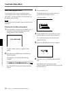
Item Settings
VIDEO
IN
Selects
the
signal
to be
recorded
onto the
internal
VCR.
CAM (normal value)
Records the signal shot by this camcorder.
EXT
Records the signal input from the GEN LOCK IN/
VIDEO IN connector. The image on the
viewfinder and the signal output from the
MONITOR OUT connector are switched to the
external video signal. When inputting the external
video signal, “EXT INPUT” blinks on the screen.
PRE WHT
Sets the color
temperature of the
preset white
balance.
When the filter is 3200 or CROSS:
2200 to 3200 (normal value) to 4300,
filter 5600K, 5600K + 1/8ND
When the filter is 5600K + 1/64ND:
4600 to 5600 (normal value) to 12000


