


DXC-990/990P
3-205-543-11 (1)
D:\Nouhin\DXC990UC\320554311DXC990UC\02GB-
DXC990UC\04ADJ.fm
masterpage:Left
GB
20
SYSTEM Menu
SYSTEM Menu
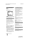
The SYSTEM menu is used to set the items
relating to the system of the camera and
selection of output signals.
Switches the baud rate of the REMOTE
connector.
Sets to any of 19200, 9600, 4800, 2400
and 1200.
Set to 9600 when the RM-C950 remote
control unit is connected.
When the CMA-D3/C3CE is connected to
the camera using the CCMC-3MZ
connecting cable, “CMA-D3” will appear
and you cannot select the baud rate.
Selects the RGB (R/G/B) or component (Y/
CR/CB) signal output from the RGB/SYNC
connector (D-sub 9-pin).
Selects the VBS or Y/C signal output from
the RGB/SYNC connector (D-sub 9-
pin).
When the CMA-D3/C3CE is connected to
the camera with the CCMC-3MZ connecting
cable, the item does not function.
Selects the sync signal output from the RGB/
SYNC connector (D-sub 9-pin).
C. SYNC
Outputs the composite sync signal.
WEN (WEN 1-3)
Outputs the WEN signal. When connecting
peripheral equipment, the signal is used as
trigger pulse output to the equipment.
Switching WEN 1 to 3 provides a different
pulse signal phase.
For the timing chart of the WEN pulse signal
for each setting, see page 39.
When TRIGGER in the GENERAL menu is
set to OFF, D-SUB SYNC is always set to
WEN and you cannot select a different
phase.
POLARITY
Selects the polarity of the pulse signal.
: Negative
: Positive
When the CMA-D3/C3CE is connected to
the camera with the CCMC-3MZ connecting
cable, you cannot select C. SYNC.
Adds a sync signal to the G signal or R, G
and B signals output from the RGB/SYNC
connector.
OFF
No sync signal is added to an output signal.
G
Adds a sync signal to the G signal output
from the RGB/SYNC connector.
BAUD RATE
Note
D-SUB OUT
D-SUB VIDEO
Note
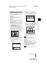
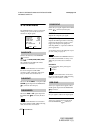
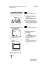
<SYSTEM>
>BAUD RATE
D-SUB OUT
D-SUB VIDEO
D-SUB SYNC
RGB SYNC
12P CONNECTOR
[A]
9600
R/G/B
VBS
C.SYNC
G
IN
Select Back
MENU
D-SUB SYNC
Note
Note
RGB SYNC