


DXC-990/990P
3-205-543-11 (1)
D:\Nouhin\DXC990UC\320554311DXC990UC\02GB-
DXC990UC\03OVER.fm
masterpage:Left
7
GB
Location and Functions of Parts and Controls
Overview
Location and
Functions of Parts
and Controls
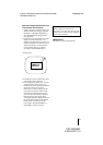
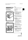
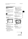
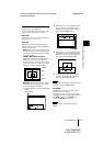
1 Boss
Attach the supplied lens mount stopper
to prevent the lens from getting loose.
2 Lens Mount
Attach a zoom lens or microscope
adaptor.
3 Mount lever
Fasten the lens by turning the mount
lever clockwise after attaching the lens.
4 Installation/tripod holes (top
and bottom panels)
Use these holes when attaching the
camera to a wall or ceiling, or a tripod.
(screw:
1
/4
″, UNC20)
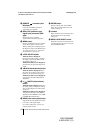
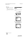
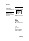
5 TRIG IN connector (BNC type)
Connects to a commercially available
slave unit by converting to BNC type in
strobe mode.
6 RGB/SYNC connector (D-
sub 9-pin)
Outputs RGB signals and their
respective sync signals.
Use the CCXC-9DB/CCXC-9DD/
CCMC-9DS connecting cable for the
connection with the CMA-D2/D2MD/
D2CE/D2MDCE camera adaptor.
For connection with the CMA-D3/
D3CE camera adaptor, use the CCMC-
3MZ connecting cable.
7 LENS connector (6-pin)
Connects to a lens cable when attaching
the 2/3-inch zoom lens. This connector
is not used for the 1/2-inch zoom lenses.
8 VIDEO OUT connector
(BNC type)
Outputs a composite video signal.
9 DC IN/VBS (DC input/
video signal output) connector
(12-pin)
Connects to the CMA-D2/D2MD/
D2CE/D2MDCE/D3/D3CE camera
adaptor. Inputs the DC power and
outputs the VBS signal.
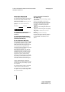
Front Panel/Top Panel
Rear Panel
1
2
3
4
VIDEO OUT
DC IN/
VBS
REMOTE
LENS
TRIG IN
MENU
BLACK
FILE
SELECT WHITE
GEN LOCK
MENU LOCK
BARS
ENTER
OFF
ON
RGB/SYNC
5
6
7
8
9
0
qa
qs
qd
qf
qg
qh
qj
qk
ql