


DXC-990/990P
3-205-543-11 (1)
D:\Nouhin\DXC990UC\320554311DXC990UC\02GB-
DXC990UC\04ADJ.fm
masterpage:Left
21
GB
SYSTEM Menu
Adjusting and Setting with Menus
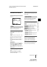
RGB
Adds sync signals to the G, B and R signals
output from the RGB/SYNC
connector.
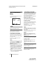
Switches the input and output of the DC
IN/VBS connector (12-pin) and selects
the output signal.
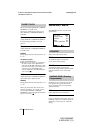
IN
Functions as the input connector.
OUT
Functions as the output connector.
SIGNAL
Selects the output signal from the DC
IN/VBS connector.
HD/VD: Outputs the HD/VD signal.
C. SYNC: Outputs the composite sync
signal.
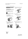
When the CMA-D3/C3CE is connected to
the camera with the CCMC-3MZ connecting
cable, you cannot set this item. Switch
between input and output with the IN/OUT
switch on the CMA-D3/D3CE camera
adaptor.
For details, refer to the operating
instructions of the CMA-D3/D3CE.
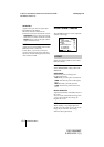
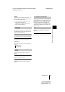
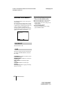
The following items appear.
Adjusts the horizontal phase and SC
(subcarrier) phase to synchronize the camera
operation with the reference signal.
H. PHASE
Adjusts the horizontal phase within the
range from –20 to +127.
SC. PHASE ROUGH
Roughly adjusts the subcarrier phase by
setting to 0° or 180°.
SC. PHASE FINE
Finely adjusts the subcarrier phase within
the range from –127 to +127.
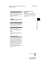
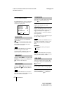
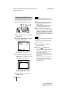
The following item appears.
Adjusts the horizontal phase to synchronize
the camera operation with the reference
signal.
H. PHASE
Adjust the level within the range from –20 to
+127.
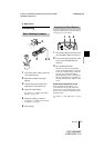
Turn on the external sync signal generator
after all equipment is switched on.
12P CONNECTOR
Note
When an External Sync
Signal (VBS Signal) Is Input
(VBS Lock)
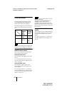
When an External Sync
Signal (HD/VD Signal) Is Input
(HD/VD Lock)
Note