


DXC-990/990P
3-205-543-11 (1)
D:\Nouhin\DXC990UC\320554311DXC990UC\02GB-
DXC990UC\06INST.fm
masterpage:Left
31
GB
Connections
Installation and Connections
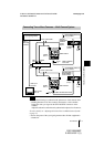
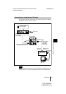
• Perform the following to synchronize the picture tone of the cameras when
switching between two or more cameras connected to a video switcher:
-Supply the same sync signal to the GEN LOCK IN connectors on the
cameras.
-Adjust the subcarrier and horizontal synchronization phases for all cameras.
For more details, see “Adjusting the Picture Tone in a Multi-Camera System”
on page 25.
• Turn on the power of the sync signal generator after all other equipment is
switched on
.
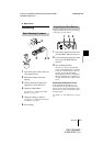
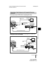
Connecting Two or More Cameras — Multi-Camera System
Notes
1
2
1
2
VIDEO OUT
DC IN/
VBS
REMOTE
LENS
TRIG IN
MENU
BLACK
FILE
SELECT WHITE
GEN LOCK
MENU LOCK
BARS
ENTER
OFF
ON
RGB/SYNC
VIDEO OUT
DC IN/
VBS
REMOTE
LENS
TRIG IN
MENU
BLACK
FILE
SELECT WHITE
GEN LOCK
MENU LOCK
BARS
ENTER
OFF
ON
RGB/SYNC
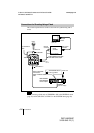
Sync signal generator
Sync
(VBS or
BS) output
connector
75-ohm coaxial cable
CMA-D2/
D2MD/D2CE/
D2MDCE
camera
adaptor
Set the MODE selector to
the [1] position.
DXC-990/990P
CAMERA
(12-pin)
GEN LOCK IN
Power
cord
VIDEO
OUT T
VBS
OUT
VIDEO
IN
DC IN/
VBS T
CCMC-12P02/05/
10/25 cable
DC IN/
VBS T
Switcher, etc.
VIDEO
IN
VBS OUT
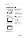
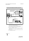
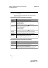
Set the MODE selector to
the [1] position.
75-ohm coaxial cable
CMA-D2/D2MD/
D2CE/D2MDCE
camera adaptor
DXC-990/990P
CAMERA
(12-pin)
Power
cord
VIDEO
OUT T
GEN LOCK IN
Video monitor,
VCR, etc.
CCMC-12P02/05/10/25 cable
Video input
connector