


44
Locations and Functions of Parts
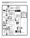
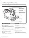
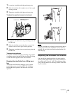
Rear
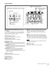
a POWER switch
CCU: Power supply will be received from the camera
control unit.
EXT: Power supply will be received through the DC IN
connector.
b Tally lamp and switch
ON: The tally lamp lights upon a tally signal input to the
connected camera control unit or a call signal generated
by pressing a CALL button.
OFF: The tally lamp is prevented from lighting.
c CCU (Camera Control Unit) connector (optical
multi connector)
Connect a camera control unit via an optical electro-
composite cable.
d SDI 1 (serial digital interface 1) connector (BNC
type)
Used for HD SDI signal output.
e CALL button
When you press this button, the red tally lamp of the RCP-
700-series Remote Control Panel or the MSU-900/950
Master Setup Unit, will light. Use to call the operator of the
RCP or MSU.
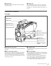
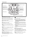
aPOWER switch
Shoulder strap fitting post (page 40)
cCCU connector
dSDI 1 connector
eCALL button
Operation panel (page 45)
Connector panel (page 46)
bTally lamp and switch
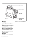
Not used