


38
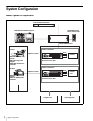
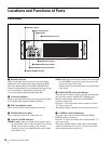
Locations and Functions of Parts
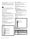
2 SD-SDI 1 to 4 (SD component SDI return video
input 1/2/3/4) connectors (BNC-type)
Four different SD component SDI return video input
signals may be received independently when the system is
operating with a field frequency of 59.94/50 Hz.
The selection of RET 1, 2, 3, or 4 is made by the return
switch of the video camera.
The type of input signal on RET 1, 2, 3, and 4 may be set
individually using the setup menu, or using the MSU-900
series Master Setup Unit.
An aspect ratio may also be selected for SD signals.
For details on the setup menu, contact a Sony service or
sales representative.
Refer also to the Master Setup Unit manual.
3 VBS 1 to 4 (VBS return video input 1/2/3/4)
connectors (BNC-type)
Four different VBS return video input signals may be
received independently.
The selection of RET 1, 2, 3, or 4 is made by the return
switch of the video camera.
The type of input signal on RET 1, 2, 3, and 4 may be set
individually using the setup menu, or using the MSU-900
series Master Setup Unit.
An aspect ratio may also be selected for SD signals.
For details on the setup menu, contact a Sony service or
sales representative.
Refer also to the Master Setup Unit manual.
e Ethernet connector (RJ-45 8-pin)
Reserved for future use.
For safety, do not connect the connector for peripheral
device wiring that might have excessive voltage to this
port.
Par mesure de sécurité, ne raccordez pas le connecteur
pour le câblage de périphériques pouvant avoir une tension
excessive à ce port.
Aus Sicherheitsgründen nicht mit einem Peripheriegerät-
Anschluss verbinden, der zu starke Spannung für diese
Buchse haben könnte.
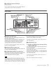
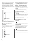
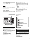
f INPUT area
1 PROMPTER 1, 2 (teleprompter input 1, 2)
connectors (BNC-type)
Input a teleprompter signal to either of the two connectors.
The input signal is output from the other connector as is
(loop-through output). If loop-through output is not used,
terminate the unused connector at 75 ohms. If the signal
used is a 1.0 Vp-p, 75-ohm signal, it may be output from
the PROMPTER OUT connector of the video camera with
a frequency bandwidth of 5 MHz, regardless of signal
format.
2 REFERENCE connectors (BNC-type)
Input an HD tri-level reference sync signal or SD reference
sync signal (black burst signal) to either of the two
connectors.
The input signal is output from the other connector as is
(loop-through output). If loop-through output is not used,
terminate the unused connector at 75 ohms.
The type of reference signal is selected using the setup
menu, or using the MSU-900 series Master Setup Unit.
For details on the setup menu, contact a Sony service or
sales representative.
Refer also to the Master Setup Unit manual.
To use the VBS signal of the HKCU1001 SD Encoder Unit
or the HKCU1003 Multi Interface Unit (when SC phase
lock is required), use an SD reference sync signal (black
burst signal).
g Spare connector (BNC-type)
Reserved for future use.
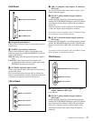
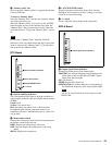
h OUTPUT area
1 SYNC (sync signal output) connector (BNC-type)
Used for output of an SD composite sync signal (with no
burst signal) or an HD tri-level sync signal from the
internal sync signal generator. (Factory setting: SD
composite sync signal)
For details on the signal selection, contact a Sony service
or sales representative.
2 CHARACTER (character output) connector
(BNC-type)
Outputs the self-diagnostic results or the setup menu as an
SD monochrome analog video signal.
3 AES/EBU connector (BNC-type)
Outputs an AES/EBU format digital audio signal input to
a video camera.
CAUTION
ATTENTION
ACHTUNG
Note