


44
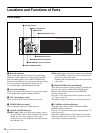
Internal Switches and Internal Boards
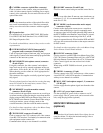
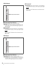
Insert the “Memory Stick” into the slot so that the labeled
side of the stick faces you.
When the “Memory Stick” is correctly set, the ACCESS
indicator lights in green. If the indicator stays dark, the
“Memory Stick” may be inserted incorrectly. Check the
stick and reinsert it. To eject the “Memory Stick,” press it
in.
Do not eject a “Memory Stick” when the ACCESS
indicator is lit in red (which means that data is being read
from or written to the “Memory Stick”). This may erase
data stored in the “Memory Stick.”
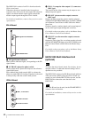
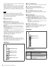
c Ethernet indicator
Reserved for future use.
d REFERENCE indicators and switch
The switch is used to select the type of sync signal to be
connected to either of the REFERENCE connectors on the
rear panel.
HD: HD tri-level reference sync signal (local setting)
RMT (remote): Signal selected on the MSU-900 series
Master Setup Unit
SD: SD reference sync signal (black burst signal) (local
setting)
When a signal is supplied to the REFERENCE connector,
the REF IN indicator lights. If the type of the input sync
signal does not match the setting on this unit, the
UNLOCK indicator will light.
e H PHASE switch
Used to adjust the H phase.
Press and hold it towards ADV to advance the phase or
towards DELAY for phase delay. The phase is advanced or
delayed only while the switch is held pressed.
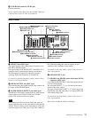
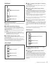
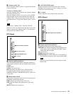
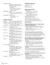
AVP Board
a CCU POWER indicator
Lights when the power voltage inside the board is normal.
b CAM LOCK (camera lock) indicator
Lights when the transaction with the video camera is
operating normally.
c CAM POWER (camera power) switch
Press downward to turn the video camera connected to this
unit on or off.
d SYSTEM indicators
/1.001 (frame frequency): Lights when the frame
frequency of the camera system is set to 1/1.001.
LINE DELAY (phase difference): Lights when the phase
difference between HD and SD outputs is set to LINE
DELAY.
Phase difference is 90H when the scan line is 1125, or
120H when the scan line is 720.
e 2WIRE CANCEL controls
When using a 2-wire intercom system, adjust the controls
to minimize the side tone level on the producer line
(PROD) and engineer line (ENG).
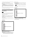
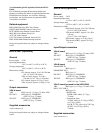
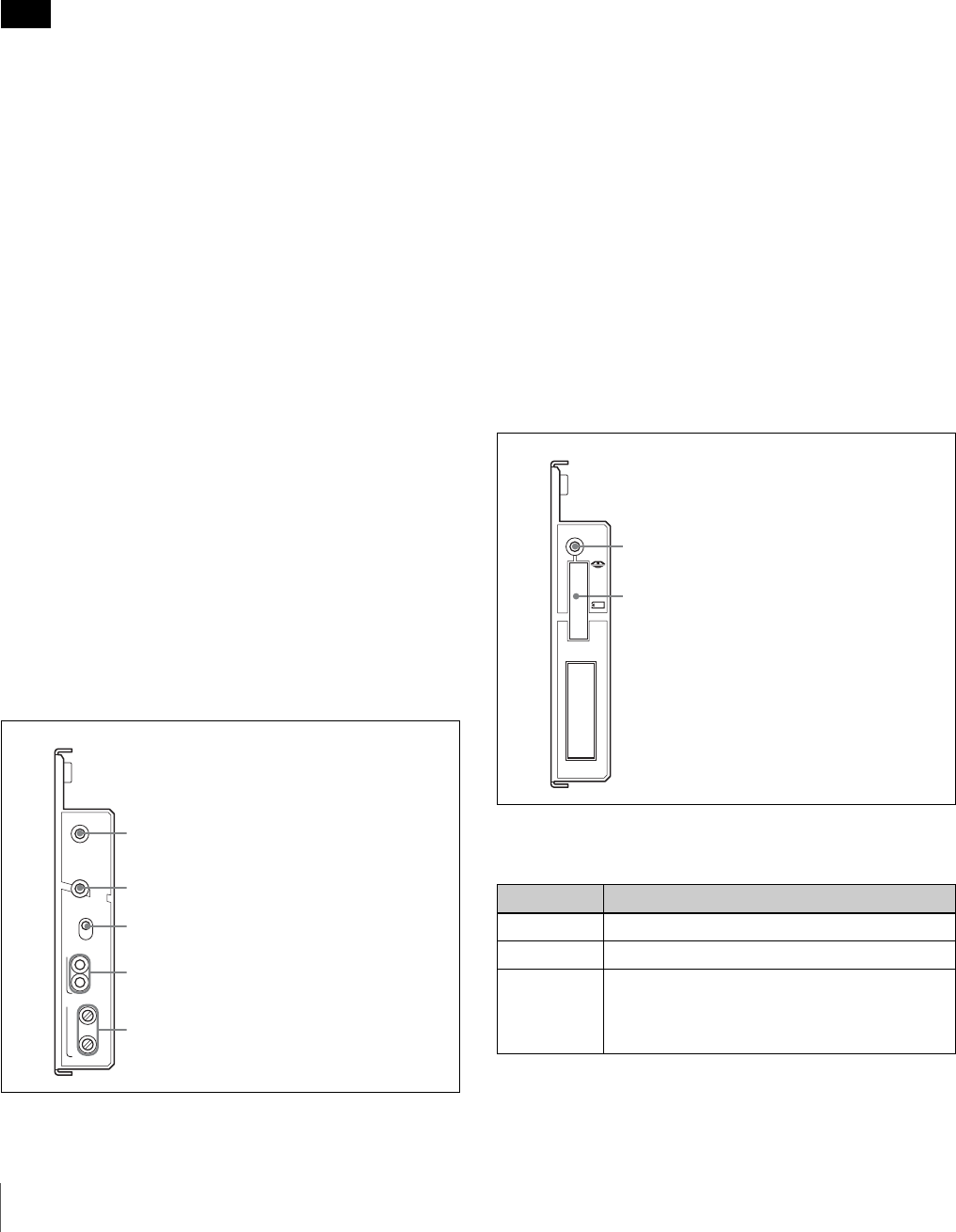
CPU Board
a ACCESS indicator
Shows the status of the “Memory Stick.”
Note
AVP
/1.001
LINE
DELAY
CCU
POWER
CAM
LOCK
CAM POWER
SYSTEM
ON/
OFF
PROD
ENG
2WIRE CANCEL
1CCU POWER indicator
2CAM LOCK indicator
52WIRE CANCEL controls
4SYSTEM indicators
3CAM POWER switch
Indication Meaning
Off No “Memory Stick” is inserted.
Lit in green There is a “Memory Stick” in the slot.
Lit in red Data is being read/written. If you eject the
“Memory Stick” during this operation, the
integrity of the data is not guaranteed. All the
data may be lost.
CPU
1ACCESS indicator
2“Memory stick” slot