


39
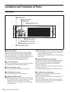
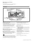
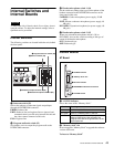
Locations and Functions of Parts
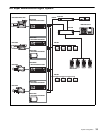
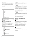
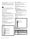
i CAMERA connector (optical fiber connector)
Used to connect a video camera, using an optical fiber
cable. All video camera signals, including power supply,
control, video, and audio, are sent and received over one
optical fiber cable.
Dust on the connection surface of the optical fiber cable
may result in transmission errors. When not connected,
always cover the end of the connector with the supplied
cap.
j Expansion slots
For installation of an optional HKCU1001 SD Encoder
Unit, HKCU1003 Multi Interface Unit, or HKCU1005
SDI Output Expansion Unit.
For details on installation, contact a Sony service or sales
representative.
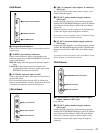
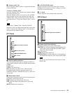
k INTERCOM/TALLY/PGM (intercom/tally/
program audio) connector (D-sub 25-pin)
Used for input and output of intercom, tally, and program
audio signals. Connect to the intercom/tally/program audio
connector of the intercom system.
l MIC REMOTE (microphone remote) connector
(D-sub 15-pin)
Using this connector, the video camera’s microphone
input level may be set by external equipment such as an
audio mixer, in five level (-60, -50, -40, -30, and -20 dB).
When shooting, set the volume to a level appropriate for
the audio conditions.
This connector also supplies a red tally signal and a green
tally signal.
The microphone input level may also be set using the setup
menu. For details on the setup menu, contact a Sony
service or sales representative.
m WF REMOTE (waveform monitor remote)
connector (D-sub 15-pin)
Used to attach to the appropriate connector on a recall-type
waveform monitor when operating the waveform monitor
display using an MSU-900 series Master Setup Unit or an
RCP-700/900 series Remote Control Panel.When using a
recall-type monitor, preset a display mode on the
waveform monitor, and then recall the mode externally.
For details on these operations, refer to the Master Setup
Unit or Remote Control Panel manuals.
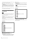
n TRUNK LINE connector (D-sub 9-pin)
Used to connect to the CCU connector on a video camera
via an RS-232C interface. Used mainly for communication
with equipment on the camera side.
Communication with up to two channels is available.
o I/O PORT connector (D-sub 15-pin)
Used for remote control using an external control device.
Use of a case wider than 42 mm can cause interference at
connectors 2, 4, 5. It is recommended that you use a JAE-
made DA-C1-J10.
p WF MODE (waveform monitor mode output)
connectors (4-pin)
Connect to the appropriate connector on a waveform
monitor when monitoring a signal in sequential mode.
A sequence signal will be output when the SEQ button on
the RCP-700/900 series Remote Control Panel is pressed,
allowing simultaneous monitoring of the R, G, and B
signals in sequential mode. When both the RCP and MSU
are in use, this connector functions as the output connector
for RCP control.
For details on these operations, refer to the Master Setup
Unit or Remote Control Panel manuals.
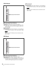
q RCP/CNU connector (8-pin)
Used to connect to an MSU-900 series Master Setup Unit,
CNU-700 Camera Command Network Unit, or RCP-700/
900 series Remote Control Panel via a CCA-5 Connection
Cable. Control signals are sent and received via this
connector.
When using an RCP-700/900 series unit, power is also
supplied.
r TRUNK A connector (12-pin)
Used to connect to the CCU connector on a video camera
via an RS-232C or RS-422A interface. Communication
with up to two channels is available.
s MIC1, MIC2 (microphone output 1, 2) connectors
(XLR 3-pin)
Used to supply the microphone signal sent from the video
camera.
t AC IN (AC power input) connector
Use the specified AC power cord to connect to an AC
power supply. The AC power cord can be secured to this
unit, using the plug holder (optional).
HKCU1001 SD Encoder Unit
(optional)
To reduce the risk of electric shock, fire or injury, do not
open the cabinet. To adjust the internal settings, refer to
qualified service personnel.
Note
Note
Note