


41
Locations and Functions of Parts
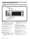
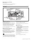
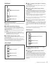
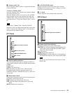
EN-B Board
a SD signal format indicators
Either of these indicators lights, corresponding to the SD
signal format.
b SUB REF (sub-reference) indicators
Either of these indicators lights, corresponding to the
reference signal input via the FRAME REF IN connector
on the VDA-B board.
REF-IN: Lights when the appropriate reference signal is
input.
UNLOCK: Lights when the reference signal is not
synchronized with the reference signal input via the
REFERENCE connector of the unit.
c SC PHASE (subcarrier phase) switch
Used to adjust the SC phase with respect to the reference
signal (black burst).
Press and hold the switch towards ADV to advance the
phase or towards DELAY for delay. The phase is advanced
or delayed only while the switch is held pressed.
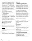
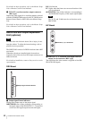
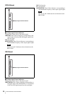
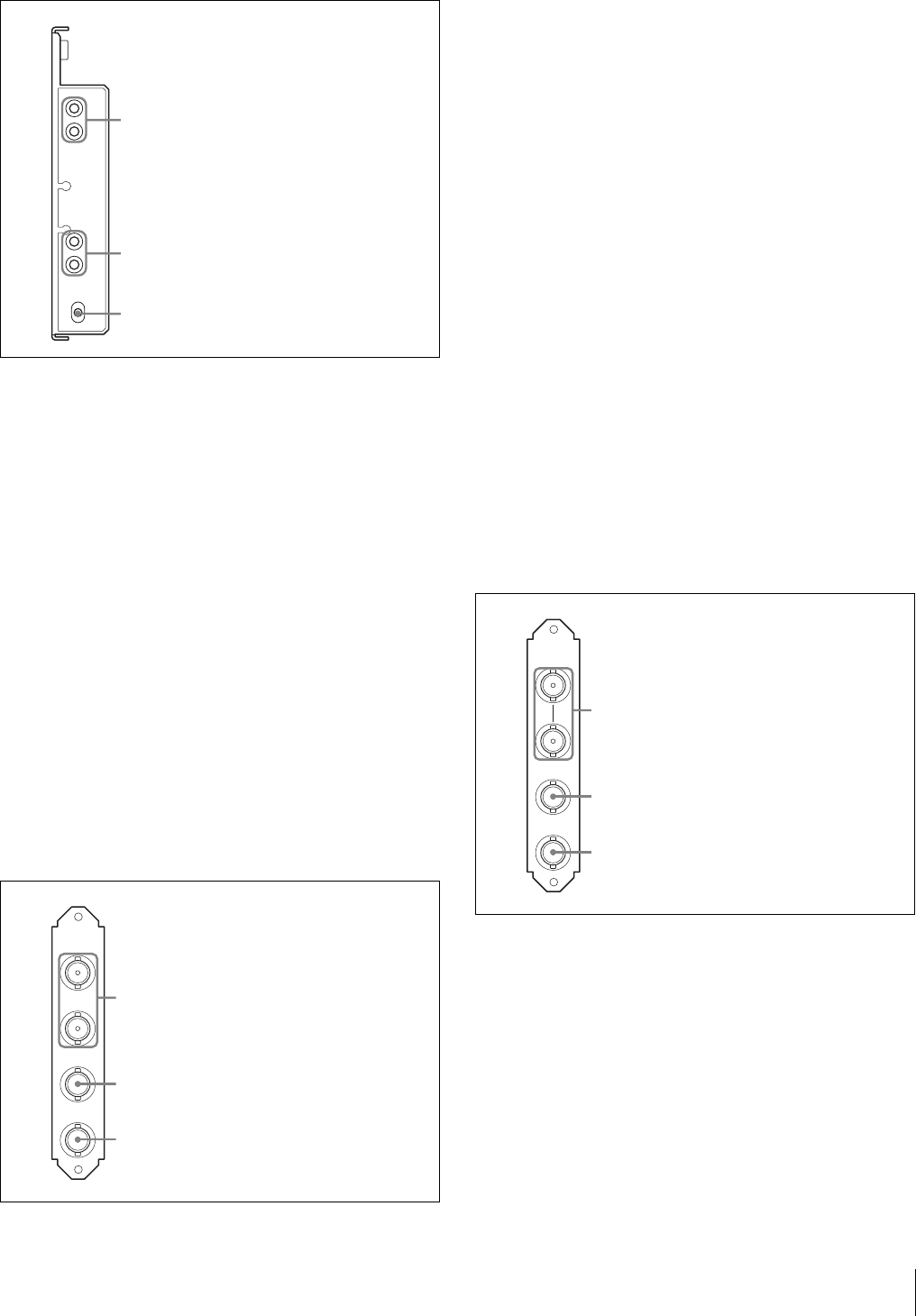
VDA-A Board
a VBS 1, 2 (composite video output 1, 2) connectors
(BNC-type)
The signal from the video camera may be output as two
analog composite signals.
b PIX OUT (picture monitor output) connector
(BNC-type)
Outputs the video signal for a picture monitor selected
with the PICTURE MONITOR button of an RCP-700/900
series Remote Control Panel or MSU-900 series Master
Setup Unit.
Character signals or marker signals can be superimposed
on the video signal output through this connector.
For details on these operations, refer to the Master Setup
Unit or Remote Control Panel manuals.
c WF OUT (waveform monitor output) connector
(BNC-type)
Outputs the video signal for a waveform monitor selected
with the WF MONITOR button of an RCP-700/900 series
Remote Control Panel or MSU-900 series Master Setup
Unit.
For details on these operations, refer to the Master Setup
Unit or Remote Control Panel manuals.
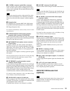
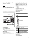
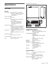
VDA-B Board
a FRAME REF IN, OUT (frame reference input/
output) connectors (BNC-type)
Not used now.
b PIX OUT (picture monitor output) connector
(BNC-type)
Outputs the video signal for a picture monitor selected
with the PICTURE MONITOR button of an RCP-700/900
series Remote Control Panel or MSU-900 series Master
Setup Unit. Character signals or marker signals can be
superimposed on the video signal output through this
connector.
EN-B
NTSC
PA L
REF IN
UN
LOCK
SC PHASE
ADV
DELAY
1SD signal format indicators
3SC PHASE switch
2SUB-REF indicators
VDA-A
1
2
PIX
OUT
WF
OUT
VBS
1VBS 1, 2 connectors
2PIX OUT connector
3WF OUT connector
FRAME
REF IN
PIX
OUT
WF
OUT
OUT
VDA-B
1FRAME REF IN, OUT connectors
2PIX OUT connector
3WF OUT connector