


43
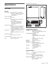
Internal Switches and Internal Boards
Internal Switches and
Internal Boards
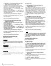
To reduce the risk of electric shock, fire or injury, do not
open the cabinet. To adjust the internal settings, refer to
qualified service personnel.
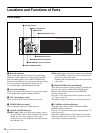
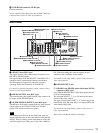
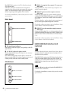
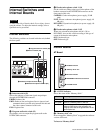
Internal Switches
The following switches are located inside the unit, behind
the front panel:
a Intercom switch (S2)
Selects the pathway of intercom signals output/input
through the INTERCOM connector.
PROD: Producer line
PRIV: Producer line and engineer line are ignored, and
communication is possible only between this unit and
the video camera connected to this unit.
ENG: Engineer line
b Program audio mix switch (S3)
Set whether or not to output the program audio to the
INTERCOM connector.
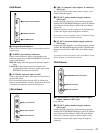
c Headset microphone switch 1 (S4)
Set the switch according to the type of microphone of the
headset connected to the INTERCOM connector on the
front panel of this unit:
CARBON: Carbon microphone (power supply, 20 dB
gain)
ECM: Electret condenser microphone (power supply, 40
dB gain)
DYNAMIC: Dynamic microphone (no power supply, 60
dB gain)
d Headset microphone switch 2 (S5)
When you set headset microphone switch 1 (S4) to
DYNAMIC, also set this switch according to the type of
output of the headset microphone.
ON: Unbalanced type
OFF: Balanced type
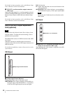
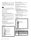
Internal Boards
AT Board
a ACCESS indicator
Shows the status of the “Memory Stick.”
b “Memory stick” slot
Insert an upgrade “Memory Stick” to upgrade the software
version of this unit.
To insert a “Memory Stick”
CAUTION
CABLE
MIC
ALARM
MAIN
POWER
CAMERA
INTERCOM
SHORT OPEN
ON
OFF
PRODPRIVENGCARBONECMDYNAMIC
PGM ON
PGM OFF
O N
S5
S3S2
S4
OFF
1
1Intercom switch (S2)
3Headset microphone switch 1 (S4)
4Headset microphone switch 2 (S5)
2Program audio mix switch (S3)
Indication Meaning
Off No “Memory Stick” is inserted.
Lit in green There is a “Memory Stick” in the slot.
Lit in red Data is being read/written. If you eject the
“Memory Stick” during this operation, the
integrity of the data is not guaranteed. All the
data may be lost.
AT
REF IN
UN
LOCK
H PHASE
REFERENCE
HD
RMT
SD
ADV
DELAY
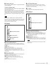
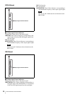
5H PHASE switch
1ACCESS indicator
2“Memory stick” slot
4REFERENCE indicators and switch
3Ethernet indicator