


142
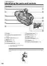
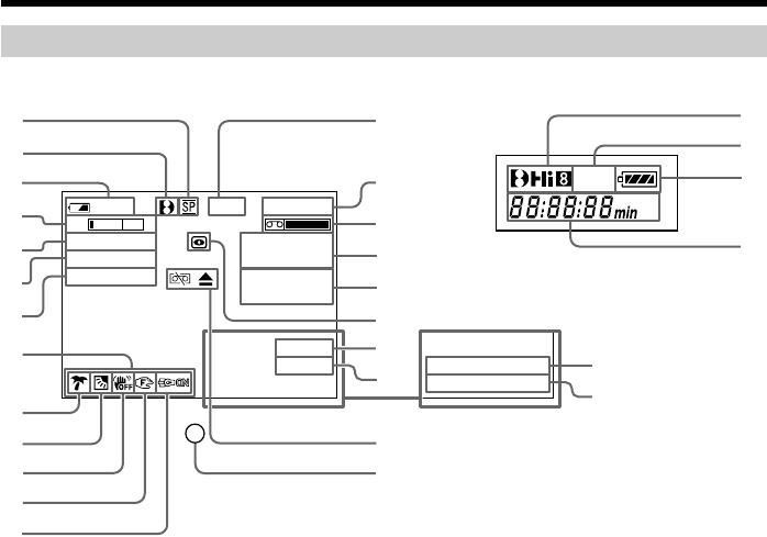
Operation indicators
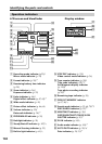
LCD screen and Viewfinder Display window
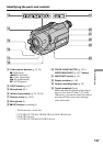
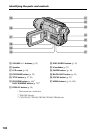
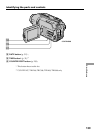
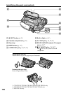
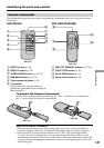
Identifying the parts and controls
1 Recording mode indicator (p.23)/
Mirror mode indicator (p. 24)
2 Format indicator (p. 28)*
1)
3 Remaining battery time indicator
(p. 28)
4 Zoom indicator (p. 26)/
Exposure indicator (p. 52)
5 Fader indicator (p. 44)/
Digital effect indicator (p. 47, 65)*
1)
6 Wide mode indicator (p. 41)
7 Picture effect indicator (p. 46, 64)
8 Volume indicator (p. 33)/
Data code indicator (p. 34)*
1)
9 PROGRAM AE indicator (p. 50)
0 Backlight indicator (p. 29)
qa SteadyShot off indicator (p. 107)*
2)
qs Manual focusing indicator (p. 53)
qd Built-in light indicator (p. 61)*
3)
qf STBY/REC indicator (p. 23)/
Video control mode indicator (p. 36)
qg Tape counter indicator (p. 28)/
Time code indicator(p. 28)*
1)
/
Self-diagnosis display indicator
(p. 118)/
Tape photo recording indicator
(p. 28)*
1)
qh Remaining tape indicator (p. 28)
qj ZERO SET MEMORY indicator
(p. 67, 96)*
1)
qk Search mode indicator (p. 32, 68, 70)*
1)
/
END SEARCH indicator (p. 32)*
4)
ql NIGHTSHOT indicator (p. 30)/
SUPER NIGHTSHOT/COLOR SLOW
SHUTTER indicator (p. 30)*
1)
w; DV IN indicator (p. 94)*
1)
wa Audio mode indicator (p. 109)*
1)
ws AUTO DATE indicator (p. 20)*
4)
/
Date indicator (p. 20, 31)*
4)
min
TW
0:00:00
REC
40
SEPIA
M. FADER
16
:
9
W
IDE
ZERO SET
MEMORY
DATE
01
SEARCH
16BIT
DV IN
4LUJ
MA65:50:21
2002
9
4
5
6
7
0
8
qa
qd
qs
3
1
2
qf
qh
ql
w;
wa
wf
ws
wd
wg
qg
qj
qk
FULL
AM
PM
2
wh
3
wj