


TANDBERG Videoconferencing System
13
Installation
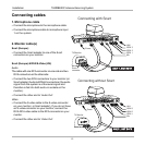
3. ISDN cables
• CConnect the ISDN cables to the ISDN sockets (S/T-interface) provided by the service provider. Your main
number will be the number associated with the socket to which ISDN cable number 1 is connected.
SOME SYSTEMS AND SOFTWARE VERSIONS DO NOT SUPPORT THREE ISDN LINES
North America: The system does not have a built-in network terminator. If your wall socket provides you with an ISDN
U-interface, you will need an NT1 between your system and your ISDN line, see Appendix 1.
W
RITE
DOWN
THE
NUMBERS
ASSOCIATED
WITH
EACH
OF
THE
ISDN
LINES
. Y
OU
WILL
NEED
THEM
LATER
TO
CONFIGURE
THE
SYSTEM
.
CONNECTING TO THE SWITCHED 56 NETWORK: WHEN CONNECTING TO THE SWITCHED 56 NETWORK YOU MAY USE ONE OF THE BRI INTERFACES
ON THE SYSTEM. PLEASE REFER TO APPENDIX 2 FOR FURTHER INFORMATION.
4. Power cable
• Connect the power cable from the system’s power connector to an electrical distribution socket.
5a. LAN cable
• To use the system on LAN, connect a LAN cable from the ‘Ethernet’ connector on the system to your LAN.
5b. Wireless LAN - Insert PC Card
• Remove the “dummy” card by pressing the ‘Eject’ button next to the slot.
• Insert the Wireless LAN PC Card.
MAKE SURE YOU INSERT THE CARD IN THE RIGHT DIRECTION (WITH THE PRODUCT LOGO POINTING UPWARDS). PUSH THE CARD INTO THE SLOT UNTIL
THE ‘EJECT’ BUTTON POPS UP.
See ‘Wireless LAN Settings’ for configuration.
NOTE
NOTE
NOTE
NOTE