


(10/16)
D4153497A
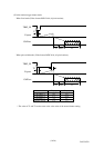
[Connector pin assignment]
(1) Gigabit Ethernet interface connector
- Connector model (Camera side) P65-P01-19V8 (Supplied by SpeedTech Corp.)
- Pin assignment
Pin No. I/O Function
1 I/O BI_DA+
2 I/O BI_DA-
3 I/O BI_DB+
4 I/O BI_DC+
5 I/O BI_DC-
6 I/O BI_DB-
7 I/O BI_DD+
8 I/O BI_DD-
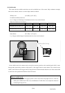
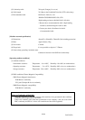
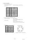
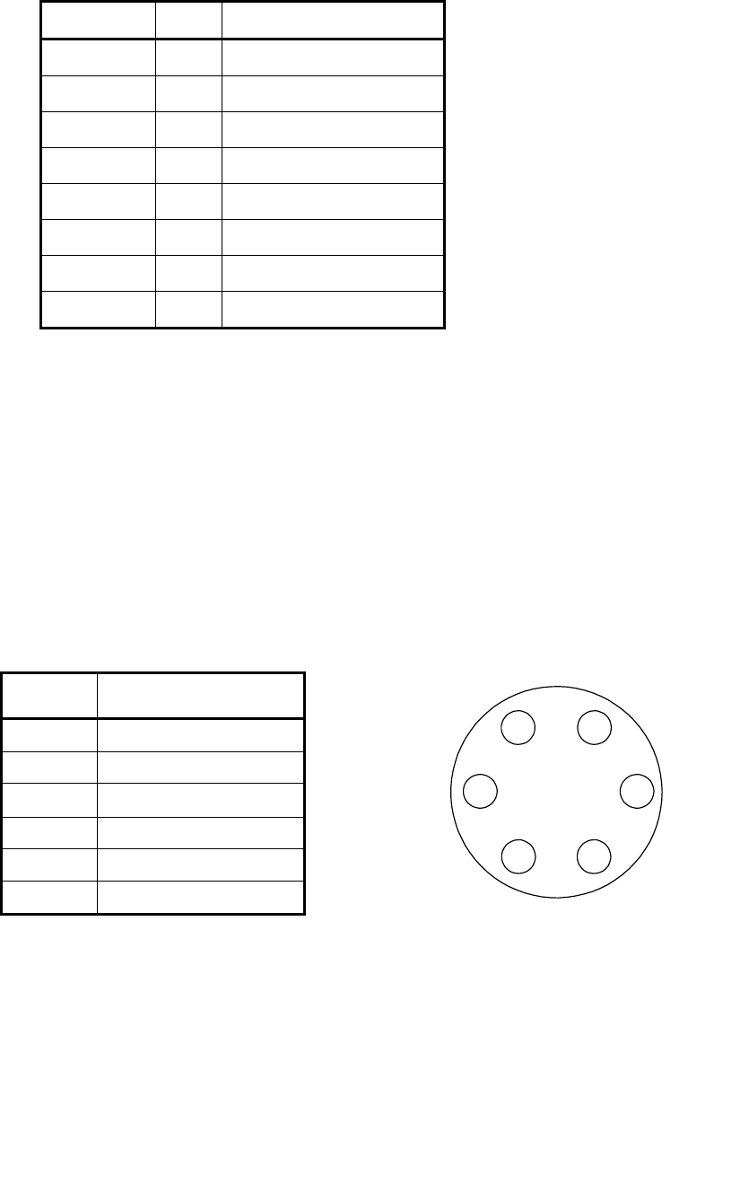
(2) Connector for Power Supply and trigger signal input
- Connector (Camera side) HR10A-7R-6PB(73)
(Supplied by HIROSE ELECTRIC CO., LTD.)
- Plug (Cable side) HR10A-7P-6S(73)
(Supplied by HIROSE ELECTRIC CO., LTD.)
* This camera cable is not an accessory of this product.
- Pin assignment
Pin No.
Signal Name
[Standard specification]
1 BUSY_OUT
2 GND
3 GND
4 TRIG_IN
5 EXPOSE_OUT
6 +12V
Above figure is connector view from insert side.
1 6
2
3 4
5
Pin number assignment