


- 25 -
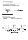
Charge begins to accumulate after the trigger input, and 1 field or 1 frame images are output. There are
three modes: 1PULSE SNR, 1PULSE SR and 2PULSE.
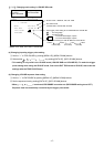
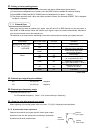
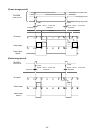
The RGB terminal trigger input and index output interface are as shown below.
Trigger input
INDEX out
CMOS out
1
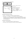
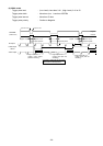
1 PULSE SNR
1 Pulse Sync Non Reset
Charge begins to accumulate after the trigger input to the RGB terminal, and 1 field images are output.
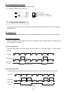
(a) Rising edge / Falling edge mode
The exposure time is set to 0.02 ms to 16 ms on the menu.
Trigger pulse level (Low Level)Less than 0.5V , (High Level)3.4V to 5V
RGB terminal
Trigger pulse fetch timing Rising edge / Falling edge selectable
Trigger pulse width More than 2s
Trigger pulse interval More than 50ms
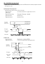
ư ư ư
INDEX
Exposure period
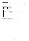
* Image output after 1 V
(Trigger pulse doesn’t
pass the VD falling.)
V
ideo output
A
pprox. 1.9s
Falling edge mode
TRIGGER
(RGB terminal)
V
D output
Index output
Exposure period Exposure period
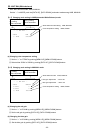
Rising edge mode
* Image output after 2 V
(Trigger pulse pass the
VD falling.)
* Image output after 2 V
(Trigger pulse pass the
VD falling.)
A
image is output at the first field
after the end of the exposure.
A
pprox. 1.9s
A
pprox. 1.9s
7'
''
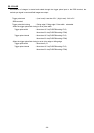
'5 EXT TRIG (External trigger)