


16
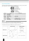
General I/O Terminal Block
This Network Camera provides a general I/O terminal block which is used to connect external
input / output devices. The pin denitions are described below.
● 12V DC is outputted from 1-pin only when connected to a power supply.
● When an AC adapter or PoE is connected, don’t supply AC24V from this terminal.
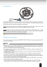
The diagrams below apply when "Digital Input" is used for an alarm input.
N.C.
N.C.
N.C.
AC24V
AC24V
GND
DI
DO
+12V
N.C.: No Connector
N.C.: No Connector
N.C.: No Connector
AC24V: Power in AC 24V
AC24V: Power in AC 24V
Pin Name Specification
N.C. No Connector
N.C. No Connector
N.C. No Connector
AC24V Power in AC 24V AC 24V ± 5%
AC24V Power in AC 24V AC 24V ± 5%
GND Ground
DI Digital Iutput OPEN/Short-to-GND
DO Digital Output Max. 40VDC, max. 400mA, isolation 2kV
+12V 12V DC Output MAX. 12V DC, 400mA
NOTE
GND: Ground
DI : Digital Input
DO : Digital Output
+12V : 12V DC Output