


VIVOTEK
User's Manual - 11
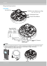
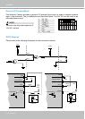
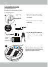
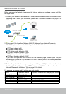
Connect power lines and if you have external devices such as sensors and alarms, make
the connection from the general I/O terminal block.
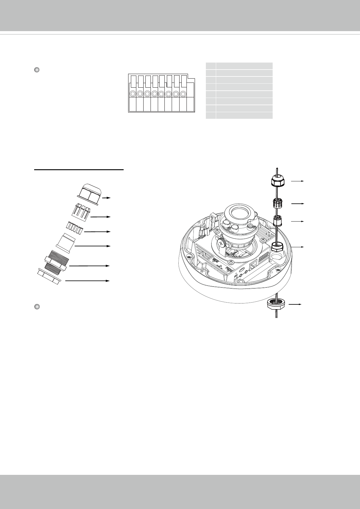
87654321
Pin Denitions
1 DC 12V-
2 DC 12V+
3 AC24V_2
4 AC24V_1
5 DI- (GND)
6 DI+
7 DO-
8 DO+ (+12V)
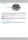
Power and IO cables pass through a waterproof connector. The Ethernet cable should be
routed through a rubber seal plug. All cables are user-supplied.
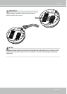
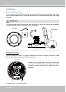
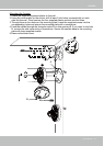
1. Disassemble the components of the
waterproof connector into parts (A) ~ (F)
as shown above.
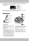
2. Place the screw nut (E) on the Power and
GPIO opening.
3. Feed the power cables through the
waterproof connector (F --> E --> D -->
B --> A) as the illustration shows. Then
connect the power cables to the power
source. Note: There are 8 holes on the
seal (D), and the widest holes with a crack
on the side are specic for power cables.
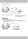
4. If you have external devices such as
sensors and alarms, feed the cables
through the waterproof connector (F --> E
--> D --> B --> A) as previously described.
Assembling Steps
Sealing Nut (A)
Housing (B)
Seals (C)
Seal (D)
Screw Nut (E)
Hex Nut (F)
Waterproof Connector
(A)
(B)
(D)
(E)
(F)
Refer to the pin denition to connect them
to the general I/O terminal block. Note:
The recommended cable gauge is 2.0 ~
2.8 mm.
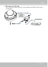
5. Push the seal (D) into the housing (B).
6. Insert the seals (C) into unused holes on
the seal (D) to avoid moisture.
7. Secure the sealing nut (A) tightly and hex
nut (F) from the bottom of the camera.