


VIVOTEK
14 - User's Manual
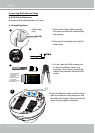
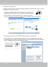
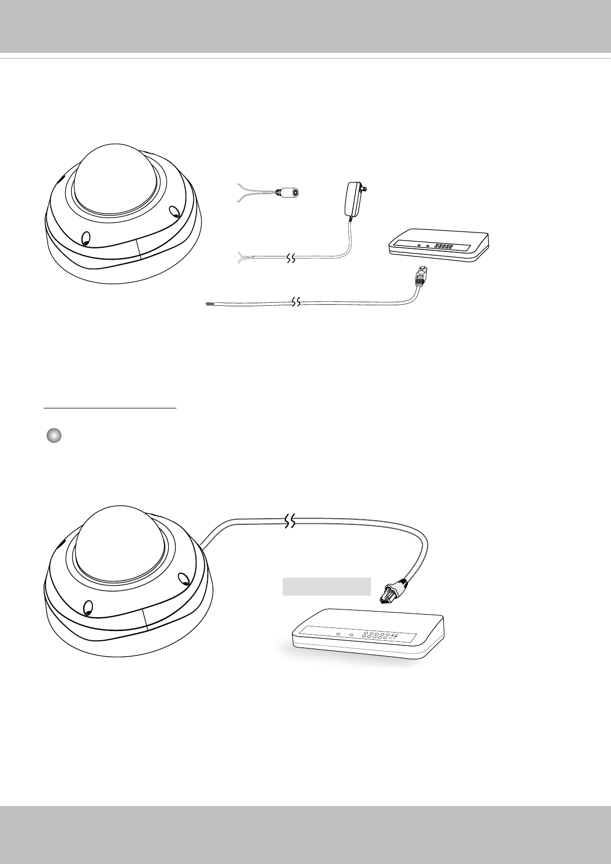
Network Deployment
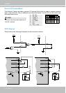
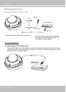
General Connection (without PoE)
1. Connect RJ45 Ethernet cable to a switch.
2. Connect the AC cables from the terminal
block as an alternate power source. The
IO cables are user-supplied.
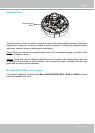
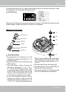
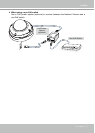
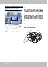
Power over Ethernet (PoE)
POWER
COLLISION
LINK
RECEIVE
PARTITION
1
2
3
4
5
PoE Switch
When using a PoE-enabled switch
The Network Camera is PoE-compliant, allowing transmission of power and data via a sin-
gle Ethernet cable. Follow the below illustration to connect the Network Camera to a PoE-
enabled switch via Ethernet cable.
POW
ER
C
O
LL
I
S
ION
L
I
N
K
RE
CEIVE
PARTITIO
N
1
2
3
4
5
Ethernet
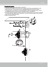
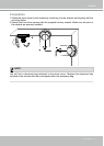
Non-PoE Switch
Pin 1
Pin 2
AC 24V±10%
DC 12V
Pin 4
Pin 3