


- 11 -
www.vivotek.com
T: 886-2-82455282
F: 886-2-82455532
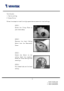
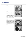
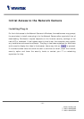
STEP 7
Assemble the Decoration
Cover to the T-Bar.
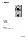
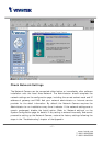
Completion
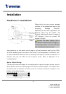
To install in Ethernet
Make sure the Ethernet is firmly connected to a switch hub. After attaching the
Ethernet cable plug in the power adapter. If the LED turns out to be steady green after
self-test, go to next paragraph “Software Installation”.
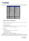
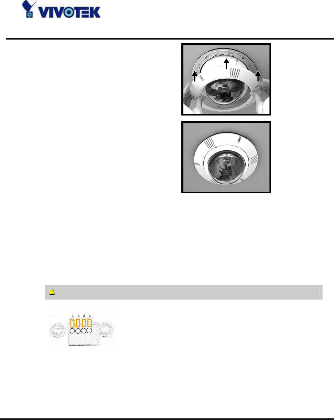
Consult with the dealer of the peripherals for correct installation.
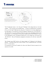
1 DI+ INPUT (Max. 50mA, 12VDC)
2 DI- INPUT (Initial state of DI is low)
3 SW_COMMON OUTPUT (open from
SW_OPEN at initial state)
(close with SW_OPEN when set DO
to ON)
4 SW_NOPEN OUTPUT (Max. 1A, 24VDC or
0.5A, 125VAC)