141
MVP MANUAL
FG Frame Ground
Tx Trandmitted Data
Rx Received Data
RTS Requenst to Send
CTS Clear to Send
DSR Data Set Ready
SG Signal Ground
1
14
25
13
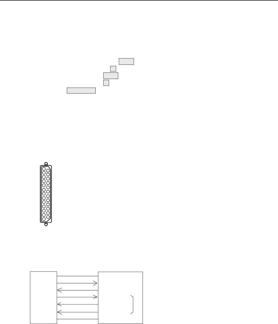
Connection with External Computer
<External Computer Side> <Video Processor Side>
Straight RS-232C IN
FG 1 1 FG
TxD 2 2 RxD
RxD 3 3 TxD
RTS 4 4 CTSl
CTS 5 5 RTSl
DSR 6 6 DSRl
SG 7 7 SG
*
* Pins 4, 5 and 6 are short-circuited inside.
Pins not shown in the diagram are NC.
Signal name
2. CONNECTION WITH MVP EXTERNAL COMPUTER
• Refer to Chapter 4.(P.105) “External Control by MPJ RS-232C” for how to adjust the MPJ.
¶ Use a RS-232C straight cable.
¶ Refer to the following diagram for connections.
¶ MVP RS-232C Settings
Baud rate : 2400, 4800 , 9600, 19200
Bit number : 7, 8
Parity : NON , ODD, EVEN
Stop bit : 1 , 2
: Setting at shipment
This setting can be changed using the DIP switches on the panel.
Refer to “Chapter 2.(P.19) MVP panel 7 Baud rate switch”.
<MVP RS-232C Pin Layout>


