


7
Chapter 7 Menu description tables
79
Item/
Data storage
Variable
range
Remarks
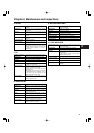
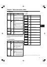
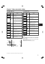
GENLOCK AUTO
For selecting the sync signal among the
camera signals.
AUTO:
If sync signals are supplied to the
GENLOCK IN connector, the camera unit
is synchronized with the reference signal
which has been input. If no sync signals
are supplied, it is synchronized with the
internal reference signal.
H PHASE COARSE –55
:
+00
:
+55
For making coarse adjustments to the
horizontal phase when setting up a system.
H PHASE FINE –100
:
+000
:
+100
For making fine adjustments to the horizontal
phase when setting up a system.
<Note>
This adjustment also affects the SC phase.
7-2-4 GENLOCK
CUFE
CUFE
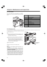
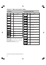
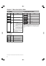
The underlining in the variable range column indicates the setting in the preset
mode.
GL PHASE HD SDI
DOWNCON
For selecting the output system that phase-
locks the signals supplied to the GENLOCK
IN connector.
HD SDI:
The HD SDI output signal is locked to the
gen-lock input. The output phase of the TC
OUT connector’s time code is aligned with
the phase of the HD SDI output.
DOWNCON:
The DOWNCON output signal is locked to
the gen-lock input. The output phase of
the TC OUT connector’s time code is
aligned with the phase of the DOWNCON
output.
<Note>
Perform the H PHASE COARSE and H PHASE FINE settings
again when the HD reference signal is switched over to the
SD reference signal as the signal supplied to the GENLOCK
IN connector.
Item/
Data storage
Variable
range
Remarks
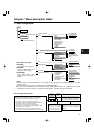
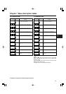
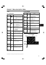
P.OFF GPS DATA HOLD
CLEAR
For selecting whether or not to hold the UMID
GPS position information while the power is
off and record the information as the data still
held as the previous value until another
measurement can be taken after the power is
next turned on.
HOLD: The data is held and recorded.
CLEAR: The data is cleared at the same time
as the power is turned off, and all
zeros (no information) are recorded
from the time the power is turned on
until the measurement is next taken.
7-2-5 OPTION MODE
CUF
REC TALLY RED
GREEN
CHAR
For selecting the method used to inform the
user that the unit is recording when a system
using an extender or other device is
configured and BOTH is selected as the 26-
PIN CONTROL menu item setting while the
system is used in the remote control mode.
RED: The red tally lamp lights.
GREEN: The green tally lamp lights.
CHAR: The letters “REC” appear on the
viewfinder.
CUFE
R GAIN –200
:
+000
:
+200
For setting the R channel gain.
Item/
Data storage
Variable
range
Remarks
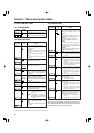
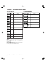
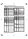
MASTER PED –200
:
+018
:
+200
For setting the master pedestal level.
MASTER DTL –31
:
+00
:
+31
For setting the H detail/V detail level.
MASTER GAMMA 0.35
:
0.45
:
0.75
For setting the master gamma in 0.01 steps.
KNEE POINT 70.0%
:
93.0%
:
107.0%
For setting the master knee position in 0.5%
steps.
KNEE SLOPE 0
:
85
:
99
For setting the knee slope.
G GAIN –200
:
+000
:
+200
For setting the G channel gain.
B GAIN –200
:
+000
:
+200
For setting the B channel gain.
R PEDESTAL –100
:
+000
:
+100
For setting the R channel pedestal level.
G PEDESTAL –100
:
+000
:
+100
For setting the G channel pedestal level.
B PEDESTAL –100
:
+000
:
+100
For setting the B channel pedestal level.
7-3 PAINT
7-3-1 ROP
SCUFE
SCUFE
SCUFE
SCUFE
SCUFE
SCUFE
SCUFE
SCUFE
SCUFE
SCUFE
SCUFE