


Download this book for free at http://www.TheArgusA.com/
60
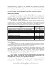
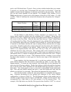
pixels, and 1200 should have 75 pixels. Once you have double-checked that your scanner
is properly set, scan the strips of aluminum foil and zoom in on the holes. Count the
number of pixels that fit lengthwise in the hole and divide by the dpi setting. That will
give you the correct diameter of your pinhole. For example, if the scanner is set to
600dpi and the hole is 9 pixels across, the diameter of the hole is 0.015 inches. (9 ÷ 600
= 0.015). Table 8-2 indicates the various hole diameters that will produce the “sharpest”
pictures.
Shutter Position
Optimum
Hole
Diameter
Approx.
Pixels at
300 dpi
Approx.
Pixels at
600 dpi
Approx.
Pixels at
1200 dpi
Shutter in storage position 0.0113 in 3.5 7 13.5
Shutter in extended position 0.0128 in 4 7.5 15.5
Variable Neck focused at 1.25 ft 0.0136 in 4 8 17
Table 8-2: Optimum hole specifications for various shutter positions
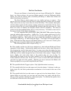
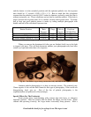
Set the Shutter to either B(ulb) or T(ime), whichever you intend to use. The
shutter speed cannot be adjusted once the aluminum foil is mounted. Ensure that the
aperture is set to f/4.5. Remove the cosmetic metal plate from the Shutter by undoing the
two screws on the Face Plate. Only the thin metal disc that says “Argus” should come
off, not the entire Face Plate. Place the aluminum foil strip, with the black side down, on
top of the Shutter where the Lens Assembly would normally fit. Ensure that the pinhole
is centered on the Shutter and that the strip in running directly between the two empty
screw holes. Carefully replace the cosmetic plate back onto the camera; this should force
the aluminum foil to tighten by the pinhole. Make certain that as the cosmetic plate
returns to its original position, the screw holes line up; if they are covered by the
aluminum foil, tear it away with a pin. The cosmetic plate can be secured in one of two
ways: it can be screwed down or it can be taped. If the screws are continuously removed
and replaced, there is a chance of damaging the threads or the head of the screw. If taped
down, make certain that it is secure. If the aluminum foil has a tendency to tear around
the edges when mounted, as some types do, line the outer edges of the aluminum foil
with tape.
Some pinholers feel that aluminum foil is not the best pinhole medium. They
prefer thicker aluminum like that found on disposable pie plates, or some other thin,
opaque material. To mount any other material, you should tape it to the aluminum foil
strip using the following technique. Rather than poking a pinhole through the aluminum
foil, cover the center of the aluminum foil with double-stick tape (tape that is sticky on
both sides). Use a hole-punch or razor to cut a hole in the middle of the double-stick
tape. Now take the pinhole medium and press it onto the double-stick tape with the
pinhole over the hole you just made. Then mount the aluminum foil strip normally.
Now that the camera is built, the only real problem is to determine the exposure
time. Exposure information for the optimal hole diameters of the various Shutter
configurations is shown in Table 8-3. The f/16 Exposure Factor is the number used to
calculate an approximate exposure time on 100 ISO film. Simply take the exposure time
recommended by a light meter at f/16 and multiply it by the exposure factor. For
example, if the light meter says that the f/16 exposure time should be 1/100
th
of a second