


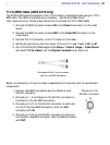
51
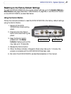
AXIS 241Q/241S - Unit Connectors
Y/C to BNC Cable (AXIS 241S only)
The AXIS 241S supports conversion from Y/C (S-video) to composite video using an Y/C to
BNC cable. The cable is available as an accessory - see the Axis Web site at:
http://www.axis.com. Follow these instructions to connect the Y/C to BNC cable:
1. Connect the BNC connector marked IN to the Video In connector on the video
server.
2. Connect the BNC connector marked OUT to the Video OUT connector on the
video server.
3. Connect the Y/C connector to the Y/C video unit (S-video).
4. Set the dip switches on the front panel of the unit to 1=on, 2=on, 3=off, 4=off.
5. Go to the AXIS 241S Web pages under Setup > Video & Image > Video Source
and select Y/C (S-video) from the Physical connector drop-down list.
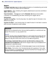
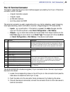
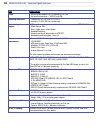
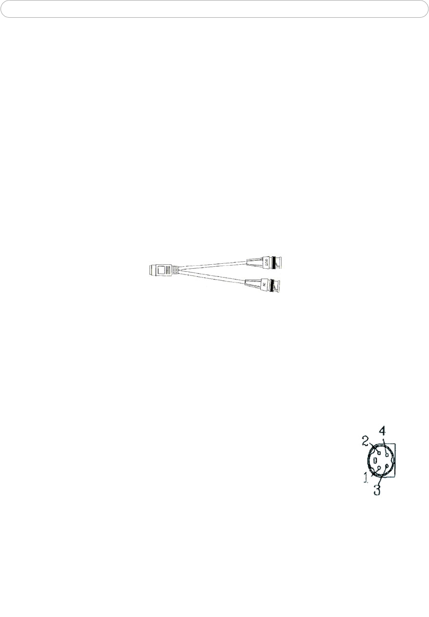
One female MiniDin 4-pol connector
split into two BNC connectors
Below is a description of how the cable is assembled for those who wish to use standard
components:
1. Use two male BNC connectors and one female 4-pole
MiniDin connector.
2. Connect pin 1, 2 and shield on the MiniDin connector to
the shield on the two BNC connectors.
3. Connect pin 3 (Y) on the MiniDin connector to centre pin
on one of the male BNC connectors, mark this BNC
connector with IN.
4. Connect pin 4 (C) on the MiniDin connector to centre pin
on the other male BNC connector, mark this BNC connector
with OUT.
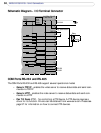
The pins on the
MiniDin connector