


8
AXIS 241Q/241S - Product Description
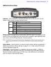
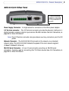
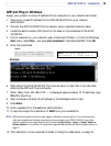
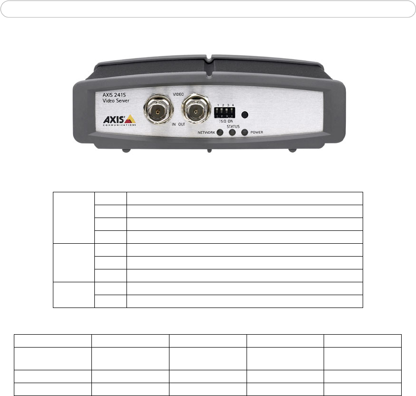
AXIS 241S Front Panel
Indicators - After completion of the startup and self test routines, the multi-colored
Network, Status, Power Indicators flash as follows:
Amber Flashes for activity on a 10 Mbit/s network
Green Flashes for activity on a 100 Mbit/s network
Red Flashes rapid red for hardware error, together with the Status indicator
None No connection
Green Normal operation
Amber Flashes during reset to factory default or at firmware upgrade
Red Flashes rapid red for a hardware error, together with the Network indicator
Green Normal operation
Amber Flashes green/amber during upgrade
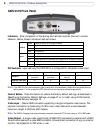
DIP Switches - upon delivery the AXIS 241S is configured for composite video input.
1 2 3 4
on off on n/a
on on off n/a
Note: If the AXIS 241S is to be connected in loop-through with other equipment, disable the input termination by
setting switch 1 to the up-position (OFF). Failure to do this may cause reduced image quality.
Control Button - Press this button to restore the factory default settings, as described in
Resetting to the Factory Default Settings, on page 47, or to install using AXIS Internet
Dynamic DNS Service, see page 15.
Video Input - Coaxial BNC connector supporting a single composite video source. The
physical connection is made using 75 Ohm coax video cable with a recommended
maximum length of 800 feet (250 meters).
Note: The AXIS 241S supports conversion between composite video and Y/C (S-video) using an Y/C to BNC cable.
Video Output - A single video loopthrough (VIDEO OUT) connected in parallel with VIDEO
IN and terminated with a coax/BNC connector. Allows direct connection of e.g. an external
monitor. Set dipswitch to OFF when in use.
Network
Status
Power
Switch
Description
75 ohm video in
termination
75 ohm video out
termination
Connects video in and
video out
Not used
Composite video input
Y/C video input