


48
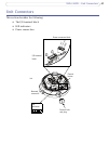
AXIS 225FD - Unit Connectors
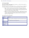
I/O Terminal Block
The 7-pin I/O terminal connector provides the interface to a solid state relay output, two
digital inputs, RS-485/422 and GND.
The terminal connector is used in
applications for e.g. motion detection, event triggering,
time lapse recording, alarm notification via email, image storage to FTP locations, etc.
• Input - Used for conn
ecting external alarm devices and triggering images for
specific alarm-based events. The input is typically connected to a motion detector
or any other external security device, and images can be uploaded whenever the
detector is activated. Connect to GND to activate.
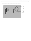
• Outpu
t - This can drive a maximum load of 50V DC at 100mA directly or heavier
loads by connecting additional relay circuitry. If the output is used with an exter-
nal relay, a diode must be connected in parallel
with the load for protection
against any voltage transients.
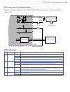
I/O terminal connector block pinout:
1 Output A On the external device output terminals (A and B), there is no distinction between positive and nega-
tive (+ and -). The terminals use a photocoupler and are elect
rically isolated from the other internal
circuitry.
The maximum load should not exceed 100mA and the max
imum voltage should be not more than 50V
DC. Note: Connecting AC to the output will damage the unit.
2 Output B
3 Digital Input 1 Connect to GND to activate, or leave flo
ating (or unconnected) to deactivate.
4 Digital Input 2
5 RS-485/422-A
(non-inverting)
A half-duplex RS-485 interface for controlli
ng auxiliary equipment.
6 RS-485/422-B
(inverting)
7 GND Ground.
Pin Function Description